Creating a Point to Point Operation

You can create a Point to Point operation. This involves defining a sequence of elementary tool motions.

This task shows you how to:

Related Topics
Point to Point

Create the Operation

You can create an operation using Point to Point command.

  1. Activate the Manufacturing Program and click Point to Point in the Prismatic Machining Operations toolbars.

    A Point to Point entity is added to the Manufacturing Program.

    The Point to Point dialog box appears directly at the Tools tab .


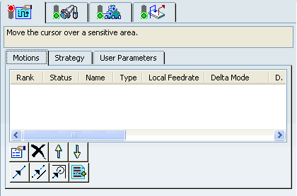
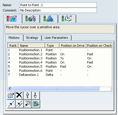
    The Motions tab allows you to define a list of elementary Goto Point, Goto Position and Go Delta motions to make up the machining operation.

  2. Select the Strategy tab , which comprises tabs Motions (to define the elementary motions making up the machining operation), Strategy, and User Parameters.

    1. Go to the Motions tab.
    2. Click Goto Point, then select a corner point on the underside of the part. Double-click to end point selection.

      The first tool motion is defined and appears in the list in the dialog box.
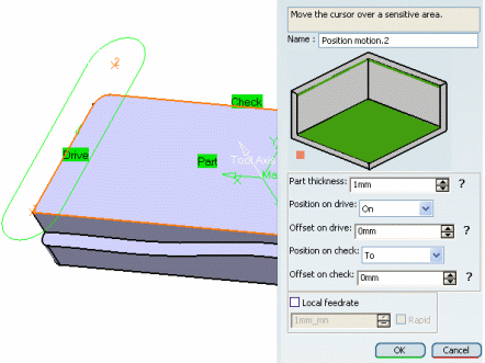
    3. Click Goto Position .

      A Sequential Motion dialog box appears to help you specify the part, drive, and check elements as well as positioning conditions (To / On / Past).

    4. Click OK when you have specified the desired elements and conditions.

      The second tool motion is defined and appears in the list in the Point to Point dialog box.

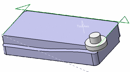
    5. Add other Goto Point, Goto Position, and Go Delta motions as shown in the figure below.


    6. Click PP words and specify the desired syntax to add PP words to the list .
    7. Move motions up or down the list using the arrows.
    8. Click Delete to remove motions.
    9. Click Properties to edit the properties of a motion.
    10. Go to the Strategy tab to specify machining parameters.
    11. Right-click any tool motion to access the contextual menu.


      • Column Order: Allows to change the header column order with Up and Down buttons.
      • Column Filter: Allows to filter the header columns.
      • Properties: Allows to modify the selected motion.
      • Delete: Removes the selected motion.
      • Cut: Cut the selected motion.
      • Copy: Copy the selected motion.
      • Invert local Axis: Allows to invert the local axis.

        Note: Invert local Axis is available only with Postionmotion.

      • Edit Local Axis: Allows to edit the local axis.
      • Use Global Axis: Allows to apply the global axis to all the points of the operation.

        Note: Edit Local Axis and Use Global Axis are available with Pointmotion and Deltamotion.

    12. Click the plane symbol in the sensitive icon to specify an indication plane and select a plane or planar face or enter X, Y, Z coordinates in the Indication Plane dialog box that appears, if required.
    13. Double-click the text in the sensitive icon to specify an offset along the tool axis.
    14. Select the axis representation in the sensitive icon to define the tool axis direction in the Tool Axis dialog box that appears.

      Note: This is the global axis, which is the default axis that is applicable to all points of the operation. However, you can specify different local axes for different points in the operation.

    15. Go to the User Parameters tab to specify user parameters.

      See Adding an User Parameter

  3. Go to the Tool tab to select a tool, in the Pocketing dialog box.

    See Specifying a Tool Element in a Machining Operation

  4. Select the Feeds and Speeds tab to specify the feedrates and spindle speeds for the operation.

  5. Select the Macros tab to specify the desired transition paths.

    See Defining Macros on Milling Operations

  6. Click Tool Path Replay to check the validity of the operation.

    See Replaying the Tool Path


    • The tool path is computed.
    • A progress indicator is displayed.
    • You can cancel the tool path computation at any moment before 100% completion.


  7. Click OK to create the operation.

    Note:

    • You can right-click the motions displayed in the authoring window to access contextual commands to insert or remove point positions and to assign local feedrates.
    • If you select a circle, its center is taken as the point to machine.
    • Points of an associated sketch can also be selected.
    • Points can be defined by clicking on a user-defined indication plane.
    • Points can be defined by entering X, Y, Z coordinates in the motion editor. Point coordinates are defined in the machining axis system.

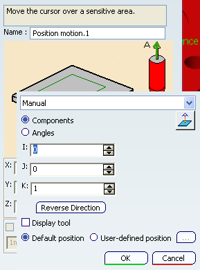
Define the Local Tool Axis

The tool axis can be defined while selecting the point itself. The tool axis orientation depends on the orientation of the selected element (line, edge). The same procedure applies to Go Delta motions.

  1. In the Strategy tab, click the tool axis in the sensitive icon and define it in the dialog box that appears.

    See Defining the Tool Axis

    This tool axis is the global axis that is applied by default to all the points of the operation, unless you define a local axis for a point.

  2. Go to the Motion tab, click Goto Point and select a point.

    The local tool axis is displayed on the point you have selected.

  3. Either:

    1. Select further points without editing their local axis.

      The global axis is applied to all the points you have selected.

    2. Right-click this tool axis and select Edit local axis in the contextual menu to define it.

      This local axis will be used on that point.

      Note: Once you have defined a local axis, this local axis (not the global axis) is applied to the next points you select, unless you define another local axis for that given point.

  4. To edit any local tool axis, if required.

    • from its contextual menu in the authoring window,

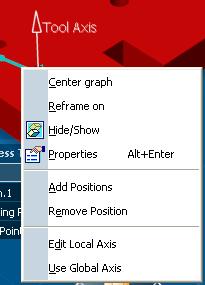
    • from its contextual menu in the dialog box,

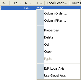
    • by clicking and modifying the tool axis in the displayed dialog box: