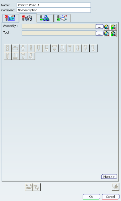
Point to Point | ||||
|
| |||
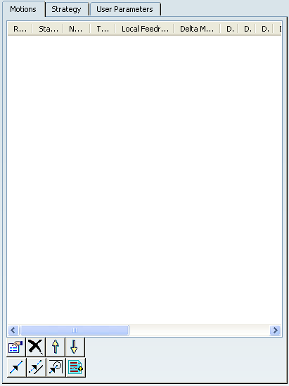
Motions Parameters
 Properties
- Edits the motion selected in the dialog box.
 Delete
- Deletes the motion selected in the dialog box.
 and
and 
- Changes the rank of the motion selected in the dialog box.
 Goto Point
- Creates a tool motion
defined by the point the tool tip has to reach. Geometry can be selected as follows:
- Direct selection on the part (points, vertices, and so on)
- Direct indication in a pre-selected surface. Only selection done within the topological limits of the surface are taken into account.
- Indication of points to be projected onto a user-defined indication plane. This indication plane is considered as infinite (it has no topological limits). This allows point indication outside the part boundaries. It is a temporary element used as an aid for selection. It is not saved after operation edition.
 Go Delta
- Creates a tool motion defined by a displacement relative to a previous
Goto Point, Goto Position or Go Delta motion location. Types of Go Delta
motion are defined from the dialog box that appears, and are as follows:
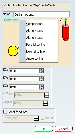
- Components: relative motion defined by DX , DY, and DZ
displacements from previous motion location.
Specifies DX , DY, and DZ displacements.
- Along X axis: relative motion along X axis (current axis system) on a specified Distance, from previous motion location.
Specifies DX displacement.
- Along Y axis: relative motion along Y axis (current axis system) on a specified Distance, from previous motion location.
Specifies DY displacement.
- Parallel to Line: relative motion on a specified
Distance, parallel to a selected Line, from previous motion
location.
Specifies Offset and Local feedrate.
- Normal to Line: relative motion on a specified Distance, normal to a selected Line, from previous motion location. The tool motion is done in a plane perpendicular to the tool axis.
Specifies Offset and Local feedrate.
- Angle to Line: relative motion on a specified
Distance, along a line computed from defined Angle and Line.
The tool motion is done in a plane perpendicular to the tool axis.
Specifes Angle, Offset, and Local feedrate.
- Components: relative motion defined by DX , DY, and DZ
displacements from previous motion location.
 Goto Position
- A tool motion is defined by positioning the tool in contact with a
part element, a drive element, and possibly a check element, while
taking To / On / Past conditions into account. The tool axis for
this motion is perpendicular to the selected part.
It is defined from the dialog box that appears:
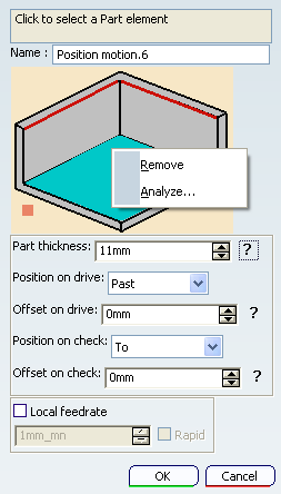
- Part
- Select part element in the authoring window.
- Part thickness
- Specifies part thickness.
- Position on drive
- Specifies To / On / Past positioning conditions.
- Offset on drive/check
- Specifies drive and check offsets.
- Position on Check
- Specifies To / On / Past / Tgt positioning conditions.
 PP words
- Insert PP words.
![]()
Strategy Parameters
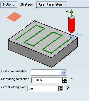
- First compensation
- Specifies the tool corrector identifier to be used in the operation. The corrector type (P1, P2, and P3, for example), corrector identifier, and corrector number are defined on the tool. When the NC data source is generated, the corrector number can be generated using specific parameters.
- Machining tolerance
- Specifies the maximum allowed distance between the theoretical and computed tool path.
- Offset along tool axis
- Defines an offset along the tool axis for all positions of the tool path (it is taken into account for all the positions of the operation).
 and drilling
  tools
can be used in this type of operation.
tools
can be used in this type of operation. ![]()
Feedrates and Speeds Parameters
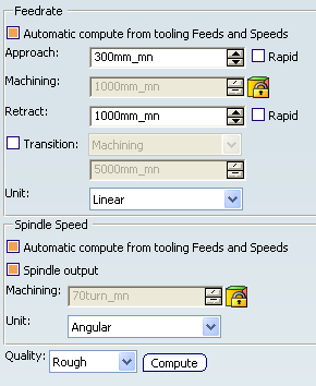
- Feedrate: Automatic compute from tooling Feeds and Speeds
- This check box allow an operation's feeds and speeds values to be updated automatically when the tool's feeds and speeds values are modified.
You can specify the following feedrates:
- Approach
- Machining
- Retract
- Rapid: In Point to Point operations, a local feedrate can be defined for all tool motions (except the first motion, which must be either RAPID or a specific feedrate). The local feedrate is applied instead of the machining feedrate during the tool motion to reach the tool position. For the operation start point, machining feedrate is taken into account.
Note:
The above feedrates can be defined in linear (feed per minute) or angular (feed per revolution) units.
- Angular: feedrate in revolutions per minute and unit is set to mm_turn.
- Linear: feedrate in feed per minute and unit is set to mm_mn.
- Transition
- You can locally set the feedrate for a transition path to a
machining operation B from a machining operation A or from a tool
change activity. This is done by selecting the Transition check box in the Machining Operation dialog box for
operation B.
For more information, please refer to the Setting a Transition Feedrate.
- Spindle Speed: Automatic compute from tooling Feeds and Speeds
This check box allow an operation's feeds and speeds values to be updated automatically when the tool's feeds and speeds values are modified.
If the Feedrate Automatic compute check box is selected and the Spindle Speed: Automatic compute from tooling Feeds and Speeds check box is not selected, then only the feedrate values can be computed. If both are not selected then automatic updating is not done.
When you modify a tool's feeds and speeds, all existing operations with the Automatic compute check boxes selected that use this tool (or an assembly using this tool) can be recomputed.
- Spindle output
- This check box manage output
of the SPINDL instruction in the generated NC data file:
- If the check box is selected, the instruction is generated.
- Otherwise, it is not generated.
Note:
The spindle speed can be defined in linear (length per minute) or angular (length per revolution) units.
- Angular: length in revolutions per minute and unit is set to mm_turn.
- Linear: length in feed per minute and unit is set to mm_mn.
- Quality
- The feed and speed values are computed according to the Quality setting on the operation.
- Compute
- Feeds and speeds of the operation can be updated according to tooling feeds and speeds by clicking the Compute button located in the Feeds and Speeds tab of the operation.
Feeds and speeds of the operation can be updated automatically according to tooling data and the rough or finish quality of the operation. This is described in Update of Feeds and Speeds on Machining Operation.
![]()
NC Macros
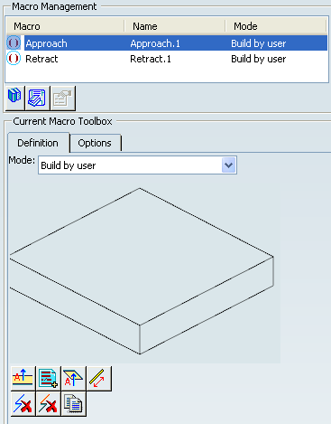
You can define transition paths in your machining operations by means
of NC macros:
- Approach: to approach the operation start point,
- Retract: to retract from the operation end point,
These transition paths are built from elementary motions.
The proposed macro mode are:
- None
- Build by user
For more information, please refer to the Defining Macros.
The following macros are available in a Point to Point operation for Build by user macro mode:
 Axial motion
 PP word
 Axial motion to a plane
 Distance along a line motion