Creating Thicknesses | |||||
|
| ||||
Click Thickness
 in the Dress-Up Features toolbar.
The Thickness Definition dialog box appears.
Important: In the Functional Modeling Part workbench, click Thickness, Local Modifier
 in the Dressup & Modifiers toolbar (Transformation Modifiers sub-toolbar). The Thickness Definition dialog box appears as shown:
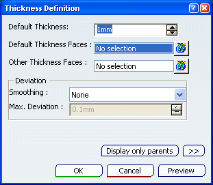
Select the faces to thicken, i.e. both faces as shown:
The faces become red and the application displays the thickness value in the geometry.
In the Default thickness box, enter 15 mm.
Note:
- A positive thickness value will add material to the feature whereas a negative one will remove material.
- In Functional Modeling Part workbench, if you extract, for example, a feature where a thickness as a local modifier is performed, this thickness will also be extracted with the feature. For more information about local modifiers, see Functional Modeling Part user's guide: Creating Dress-up and Modifier Feature.
Click OK.
The 3D shape is thickened accordingly. This creation appears in the specification tree.
In the Other thickness faces box, select the lateral face as shown.
Click More (only in the Part Design workbench) to access the deviation parameters
Click OK to close the Thickness Definition dialog box and create the thickness feature.
The length between the selected face and the resulting face is 25mm.