Analyzing Taps and Threads | ||||
|
| |||
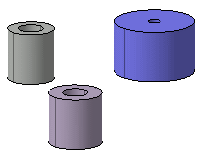
The Thread/Tap Analysis dialog box is displayed, providing display options already selected by default:
- Show symbolic geometry: shows the representations of the threads and taps in the geometry area. The representation's color can be customized via the Tools > Options > General (Display) capability (you just need to access the Visualization tab and the Selected elements option).
- Show numerical value: shows three values defined for threads and taps as follows: diameter x depth x pitch
The dialog box also displays the total number of threads and taps of the 3D shape. Two threads and one tap have been detected, as indicated in the Numerical Analysis frame.
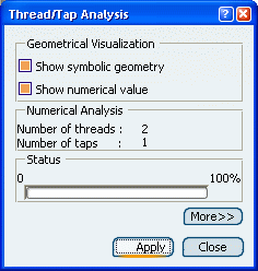
Click Apply to display the representations and the values of the threads and tap contained in the document.
The representations and the values (diameter x depth x pitch) are displayed in orange and yellow respectively:
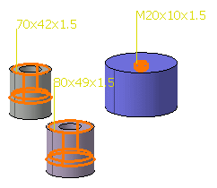
Clearing Show symbolic geometry lets you display numerical values only. In the same way, clearing Show numerical values lets you display representations only.
Important: In case the thread has more descriptions (For example, thread is created using Metric Thin Pitch standard), the brackets are applied to the values. 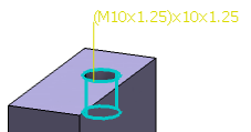
Click More to access display filters.
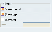
By default, the Show thread and Show tap options are selected. Clear Show thread to display taps only.
Click Apply to run the analysis. Only one tap has been detected and is therefore displayed:
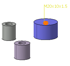
Select Show thread again to continue the scenario.
Select Diameter and enter 70 as the diameter value in the Value box.
Click Apply. The application displays only one thread with 70 as diameter value.
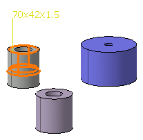
Click Close when done.