Specification Tree | ||
| ||
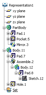
![]()
Symbols
Here are the symbols for all types of features seen in the PartDesign specification tree.

Insert
  |
Body |
 |
Solid Bodies (bodies created with application versions up to Version 5 Release 14). |
 |
Geometrical Set |
||
 |
Ordered Geometrical Set |
Depending on the chosen environment type, icons representing bodies (and partbodies) are assigned distinct colors as summarized in this table:
| Environment type | Solid body | Body | Insert Body command |
|
|
 |
 |
Solid body |
|
|
 |
|
Body |


  PartBody |
A Part Body. This type of partbody can include solids, wireframe and surface elements.
The icon identifying part bodies is:
|
 PartBody |
A solid PartBody. This type of Part Body cannot include wireframe nor surface elements. The icon identifying solid part bodies is:
|
|
Body.3 |
A Body. This type of body can include solids, wireframe and surface elements. The icon identifying bodies is:
|
|
Body.1 |
A solid body. This type of body cannot include wireframe nor surface elements. The icon identifying solid bodies is:
|
Sketch-Based Features Toolbar
 |
Pad |
 |
Groove |
 |
 |
Hole |
|
 |
Drafted Filleted Pad |
 |
Rib |
 |
Drafted Filleted Pocket |
 |
Slot |
 |
Shaft |
 |
Stiffener |
 |
Multi-Pad |
 |
Loft |
 |
Multi-Pocket |
 |
Remove Lofted Material |
Dress-Up Features
 |
Edge Fillet |
 |
Draft from Reflect Lines |
 |
Variable Radius Fillet |
 |
Variable Angle Draft |
 |
Face-Face Fillet |
 |
Advanced Draft |
 |
Tritangent Fillet |
 |
Shell |
 |
Chordal Fillet |
 |
Thickness |
 |
Chamfer |
 |
Thread |
 |
Basic Draft |
 |
Replace Face |
 |
Remove Face Feature |


