Location of Operating Bodies in Boolean Operations | ||
| ||
Different Possible Locations
You can locate the operating body at different locations depending on the type of the body you selected first.
When performing a Boolean operation, whatever the operation type you perform (Add, Assemble, Intersect etc.), the second body you select -referred to as "operating body" hereafter - for performing a Boolean operation can be located at two different locations depending on the type of the body you selected first.
Operating bodies remain at their initial locations in the trees if:
- there is an interruption of the sequential construction of the geometry
OR
- if they are used to perform a mixed Boolean operation
Otherwise, they are moved just below the Boolean operation node.
![]()
Boolean Operations Versus Mixed Boolean Operations
There is a difference between Boolean operations and mixed Boolean operations.
To anticipate the location of operating bodies, remember that two displays are possible for non-mixed Boolean operations, whereas there is only one possible display for mixed Boolean operations.
Non-mixed Boolean Operations
When performing a non-mixed Boolean operation, the application can display the specification trees in two different ways:
- If the sequential construction of the geometry is valid, the Boolean operation node contains the operating body. As shown in the scenario described in Assembling Bodies, for example, the second body selected is moved just below the Assemble node. It is "aggregated".
- Conversely, if there is an interruption of the sequential construction of the geometry, the Boolean operation node never contains the operating body. The operating body remains at its initial location in the tree.
Mixed Boolean Operations
A hybrid design environment makes it possible to perform mixed Boolean operations. By "mixed", we mean operations between bodies and solid bodies, or between ordered geometrical sets and solid bodies, or even between geometrical set and bodies (and vice versa). In the case of mixed Boolean operations, the Boolean operation node never contains the operating body.
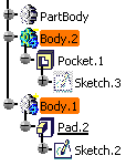
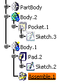
In the example below, an Assemble operation is performed between Body.2 and Body.1. Body.2 and Body.1 are two different body types. Body.2 is created in a hybrid design environment whereas as Body.1 is a solid body.
| Mixed Configuration | Mixed Boolean
Operation Body.2 being the second body selected, it remains at its initial location in the tree. |
|
 |
-> |
 |
Mixed Configurations
The tables below list all possible mixed configurations and all related behaviors.
| Body Selected First | Operating Body | Display in the tree for Operating Body | |
| Solids | Solid body | Solid body | Under Boolean operation |
| Solid body | Body | At its original location | |
| Body | Body + sequential construction of the geometry | Under Boolean operation | |
| Body | Body + interruption of the sequential construction of the geometry | At its original location | |
| Body | Solid body | At its original location |
| Body Selected First | Operating Body | Display in the tree for Operating Body | |
| Volumes | Geometrical set + Volume | Body | At its original location |
| Geometrical set + Volume | Solid body | At its original location | |
| Ordered geometrical set + Volume | Body+ interruption of the sequential construction of the geometry | At its original location | |
| Ordered geometrical set + Volume | Body | Under Boolean operation | |
| Ordered geometrical set + Volume | Solid body | At its original location |
![]()
Pre-V5R15 SP1 Mixed Boolean Operations
The pre-V5R15 SP1 mixed Boolean operations have a different display. You can obtain a right display:
Documents including mixed Boolean operations created with software versions anterior to V5R15 SP1 display Boolean operations nodes in a way different from what described just above: operating bodies are located under Boolean operations.
To obtain the right display, just proceed as follows:
-
Double-click the Boolean operation node of interest. The corresponding dialog box appears as well as a message warning you that the operating body will be moved under the part.
-
Click OK in the dialog box that appears. The node then reflects the new display.
![]()
Restrictions
There are certain restrictions you need to remember when locating operating bodies in Boolean operations.
- Mixed Boolean operations are not allowed for generating UDFs (User Defined Features) nor Power Copies.
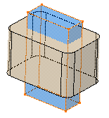
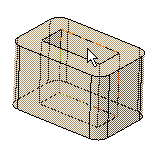
- When performing a Boolean operation, the color of the operating
body is not propagated to the faces resulting from the operation.In this example, the operating body is blue.
 Once a Remove operation has been done, the resulting faces are not blue.Additionally, the Properties capability is not available for the faces produced by the Boolean operation (an error message is issued when attempting to launch the command). Likewise, the Graphic Properties toolbar is grayed when such faces are selected.