Click Positioned Sketch
 .
.
The Sketch Positioning dialog box appears.
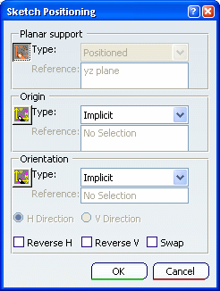
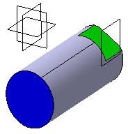
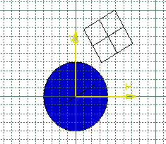
You will position the sketch absolute axis as follows:
- its origin will be on the axis of revolution,
- its horizontal (H) direction will be parallel to the
flat face,
- its vertical (V) direction will be normal to the flat
face.
Move the mouse over the pad if you simply want to select
the plane as you would do for a sliding sketch.
Deactivate the Smart Mode
 if
you want to select the support manually.
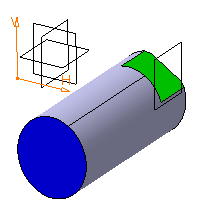
Now choose the Origin and Orientation of the sketch.

Activate the Smart Mode for any of them if
you want to move the mouse over the pad and choose either the origin
or the orientation. For detailed information, see
Part Design User's Guide: Modifying 3D Shapes: Changing a Sketch Support: More about Changing Sketch Supports.
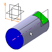
The absolute axis of the sketch is now positioned on
this axis. Its orientation has not changed.
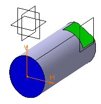
You will now specify the absolute axis orientation according
to an edge of the flat face. Select Parallel to line in the
Type field of the Orientation frame.
Select an edge of the flat face.
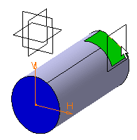
The absolute axis of the sketch is now oriented like
the selected edge.
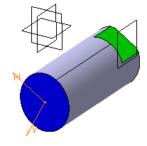
Now invert the H direction and make the V direction
normal to the flat face. To do this, start by selecting V Direction
in the Orientation area to specify that you want the orientation
to be defined according to the V direction.
Select Reverse V to revert the V direction and select
Swap to swap H and V directions.
The sketch is now positioned as wanted.
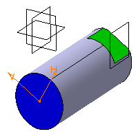
Click OK to validate and exit the Sketch
Positioning dialog box.
You are now in the Sketcher workbench and ready to sketch a profile
for the retaining bracket.
Note:
In this scenario, you did not create any constraints
on 2D geometry. The geometry is therefore under-constrained. Yet, if
you move or resize the 3D shape (no matter how significantly), the profile
you sketched will remain absolutely unchanged. Its shape will not be
altered: thanks to the fact that the position of its absolute axis is
explicitly defined, it is automatically pre-positioned in 3D before
its 2D resolution.
Click Exit Workbench  .
.
You are now back in Part Design workbench.