Getting Planning Data | |||
| |||
From any Manufacturing Planning session:
- Alternatively, open an existing Machining Process or PPR context .
 By default,
the
Activities Process Tree opens
automatically.
By default,
the
Activities Process Tree opens
automatically.
- The planning data (ElementaryEndItem and GeneralSystem in our example) are present under the PPR Context but need to be imported in the machining process.
- Alternatively, open an existing Machining Process or PPR context .
Right-click the Part Operation and select Get planning data in the contextual menu.
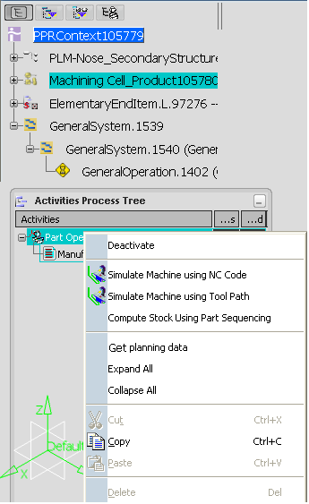
The Get Planning Data dialog box is displayed.
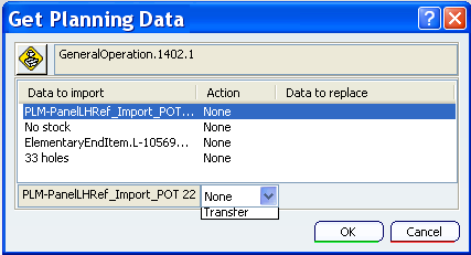
The data listed in the dialog box are respectively:
- the part to machine,
- the stock (in our example, there is none),
- the part/STL attached to the planning operation, supporting the holes,
- the part containing the geometrical definition of the holes to be machined. The holes are defined as a set of points, with the origin coordinates, the axis, the diameter, the depth and the drilling type (pre-drilling, drilling, not to be machined). This definition is used as is, with no coherence check, nor adjustment (e.g. the depth of the hole is not adjusted to the part height, ...)
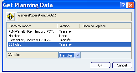
Select each element listed in the dialog box:
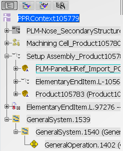
A Setup Assembly is created. It contains the following elements defined from the planning data:
- the part to machine,
- the part supporting the holes,
- the part containing the geometrical definition of the holes to be machined. A Machinable Axial Feature is created for each hole imported. You can use it to create patterns.
Note: Our example contained no stock, so it has not been created.
Note: Any modification of the planning data is not propagated to the data imported in the Setup Assembly. If need be, it must be re-imported.