Tool Path Editor | ||||
|
| |||
Edition functions:
 Point Modification,
 Area Modification,
 PP Word Modification.
Transformation functions:
 Translation,
 Rotation,
 Mirror,
 Reverse.
Others:
 Connection,
 Approach and Retract Modification,
 and
and  Display On/Off.
Point Modification
- Selection
- Offers icons corresponding to different selection options:
 Multi-selection
- Lets you select several points one by one.
 Selection by sweep
- Lets you select several points by sweeping the cursor over them.
 Selection between 2 points
- Lets you select all the points between two picked points.
Note: The two points must belong to the same tool path.
 Selection by polyline
- Lets you select all the points inside a polyline.
 Reverse
- Reverses the current selection.
 Reset
Reset- Resets all the selections.
- Action
- Offers icons to cut or modify the points:
- Visualize Circles
-
- When selected, this option visualizes circles as such,
- When cleared this option visualizes circles as polylines.
- x,y,z
- Lets you enter the new coordinates of the selected point.
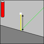
- Distance
- This parameter is displayed in the authoring window once you have selected a portion of the tool path.
- Pull the arrow to draw the selected point to its new position.
- Use the contextual menu of Distance to select the
translation direction of the selected point:
- Along X axis,
- Along Y axis,
- Along Z axis,
- Along tool axis,
- Along last polyline, i.e. along a line created between the previous point and the point selected,
- Along next polyline, i.e. along a line created between the next point and the point selected.
- Or double-click the word Distance and enter the
distance in the box.
![]()
Area Modification
-

- Moves the selected area.

- Cuts the selected area.
-

-
Modifies the feedrate either locally or globally.
- You can choose a new feedrate type:
- If the feedrate type is local, you can enter its value:
- You can choose a new feedrate type:
 Multi-selection
- Lets you select one point.
- Selection between two points
- Lets you select all the points between two picked points.
Note: The two points must belong to the same tool path.
- Selection by closed contour
- Lets you select all the points within a closed contour.
 Selection by polyline
- Lets you select all the points inside a polyline.
 Selection of collision points
- Lets you select the collision points.
- reverse
- Reverses the selection.

- Starts the Area Selection Option dialog box:
- Before/In selected geometry
- The area of tool path selected is before the point selected, or between the two points selected.
- After/Out selected geometry
- The area of tool path selected is after the point selected, or outside the two points selected.
- Copy transformation
- Copies a cut area of the tool path in the process table.
![]()
PP Word Modification
-

- Selects the previous PP Word.

- Selects the next PP Word.
-

- Inserts a new PP Word in the tool path.

- Deletes a PP Word.

- Edits a PP Word.
![]()
Translation
Translation is performed via the arrow displayed in the authoring window.
- Distance
-
- Pull the arrow to draw the selected area of the tool path to its new position.
- Use the contextual menu of Distance to select the translation direction of the selected area of the tool path.
- Or double-click the word Distance and enter the distance in the box.
![]()
Connection
- Selection
- Offers icons corresponding to different selection options:
- Multi-selection
- Lets you select several points one by one.
- Selection by sweep
- Lets you select several points by sweeping the cursor over them.
- Selection between 2 points
- Lets you select all the points between two picked points.
Note: The two points must belong to the same tool path.
- Selection by polyline
- Lets you select all the points inside a polyline.
- Reverse
- Reverses the current selection.
- Reset
- Resets all the selections.
- Connection Mode
- Offers icons corresponding to different connection options:
- Distance
- is available for a direct connection,
- defines the distance the tool will rise to.
- X, Y, Z and Nx, Ny, Nz
- are available for a connection through a plane,
- define the safety plane through a point and a normal. The connection will go through the point in the plane.


![]()
Approach and Retract Modification
- Delete
- Filter
- Lets you filter the type of the path you want to delete:
- Approach,
- Retract,
- Linking passes,
- Between paths.
Note: You can select several types.
- Remove from whole tool path
- Removes the whole tool path.
- Remove from area inside polygon
- Removes the selected portion of the tool path. You select this portion by drawing a polygon on the tool path.
- Add/Modify
- Selection offers icons corresponding to different selection options:
- Multi-selection
- Lets you select several points one by one.
- Selection by sweep
- Lets you select several points by sweeping the cursor over them.
- Selection between 2 points
- Lets you select all the points between two picked points.
Note: The two points must belong to the same tool path.
- Selection by polyline
- Lets you select all the points inside a polyline.
- Reverse
- Reverses the current selection.
- Reset
- Resets all the selections.
- Apply
- Applies the selection mode.
- Approach/Retract
- The Mode can be set to:
- Along tool axis:
The tool moves along the tool axis for a given Distance.
- None: No approach/retract.
- Back: The tool doubles back like an arrow above the cutting tool path.
You can either define this type with Cartesian coordinates
(Distance and Height) or polar coordinates
(Angle and Radius).
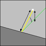
- Circular: The tool moves towards/away from the part in an arc.
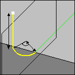
You can choose to compute the plane in which the tool moves either Automatically or Manually. The parameters that you can set are:- the Distance,
- the Angular sector,
- the Angular orientation,
- the Radius.
- Box: The tool moves across the diagonal of an imaginary box, either
in a straight line or in a curve (Linking
mode).
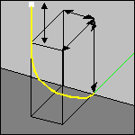
Its length is the distance that the tool will move in once it has crossed the box. The box is defined by three distance values:- the distance along the tangent (Distance/tangent),
- the distance along the tool axis (Distance/tool axis, can be a negative value) ,
- the distance along the normal axis (Distance/normal axis),
- The direction of the box diagonal is defined by the Side of normal axis, i.e. whether you want to use the normal to the Left or the Right of the end of the tool path when looking along the tool path in the direction of the approach/retract.
- Along tool axis:
The tool moves along the tool axis for a given Distance.