Adding a Grid to the 3D View | |||
| |||
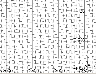
Click Resource Layout Grid in YZ Plane
 .
.In the example below, the grid appears with numbering visible thanks to the setting in the Tools > Options > Resource Definition & Layout > General tab. Y3000 means that the line is at 3000 (current unit) from the origin along the Y axis.
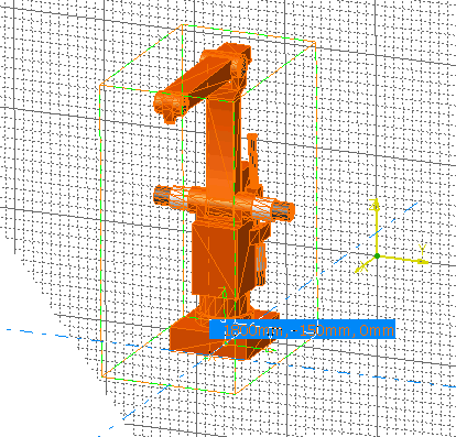
Move the robot along the grid to observe the grid expanding and contracting to follow the robot's placement.
The size of the grid can be altered using the step input box in the General Environment Tools toolbar. See Toolbars.
The grid step is defined by the step combo. However the scale of the grid is dynamic. So if the step is 200, the grid scale can be a multiple or sub-division of 200 (for example, 20000, 2000, 200, 20, 2).
This is called a dynamic (or adaptive) grid since the step changes depending on the zoom factor.
Other options for the grid can be set using the Tools > Options > Resource Definition & Layout > General tab.