Line Type Definition | ||
| ||
Defining Line Types in 2D Layout for 3D Design
The information below is specifically intended for administrators customizing standards for the 2D Layout for 3D Design workbench:
- When displaying line types in the 2D Layout for 3D Design window: the line types which are used are those defined in standards.
This is the case of all elements displayed in the 2D or 3D background of a view in the 2D Layout for 3D Design window, whether they are:
- layout elements (geometry, annotations and so on),
- 3D wireframe elements (lines, points and so on).
- When displaying line types in the 3D window (Part
Design, for example): the line types which are used
are those defined in the settings (through Tools
> Options > General > Display > Line Types).
This is the case of all layout elements (geometry, annotations and so on), when displayed in the 3D window.
- When printing a layout: the line types which are used are those defined in standards.
- When editing part layouts in the context of a product:
the line types which are used are those defined in the
standards of the current layout (even when visualizing
elements which belong to another layout).
For example, take the following scenario, where:
- the layout of Part.1 uses ISO_3D
- the layout of Part.2 uses JIS_3D
- the line type definitions are different in ISO_3D and JIS_3D.
In this case, when visualizing Part.2 in the background of the Part.1 layout, Part.2 will be displayed using the line type definitions of Part.1.
Therefore, if you want the visualization of elements to be homogeneous in the 2D and 3D windows, you need to make sure that line type definitions in the standards match line type definitions in the settings.
![]()
Defining Line Types
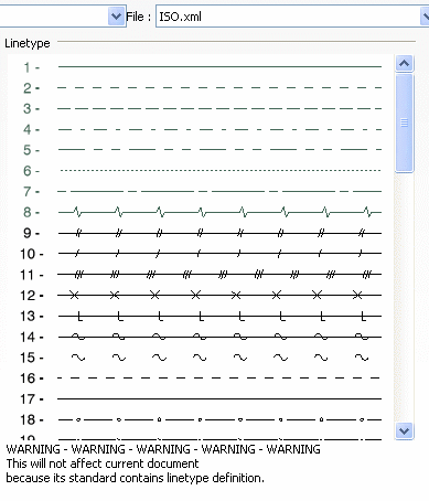
Line types can either be mono-dimensional, i.e. defined by a sequence of non-continuous segments, or bi-dimensional, i.e. defined by a polyline. Once defined, a line type can be applied to any element which supports it, either via Edit > Properties, or using the Graphic Properties toolbar.
There are 63 line type definitions in the Standards editor. You cannot
add additional instances of line type definitions. Out of these 63 definitions,
- line type definitions ranging from 1 to 8 are pre-defined with different parameters for each and cannot be customized.
- line type definitions ranging from 9 to 19 are pre-defined with different parameters for each and can be customized.
- line type definitions ranging from 20 to 63 are not pre-defined and can be customized.
| Important: From V5 R17, it is possible to assign bi-dimensional line types on all mono-parametric geometries (line, circle, spline). However, the line type 8 is an exception: it is taken into account on geometrical lines and circles. Note that you can select and apply line type 8 to any other element, however your change will not be taken into account. |
You can customize the definitions of line types ranging from 9 to 63. To do this, proceed as follows:
-
Click the Line Types node of the Standard Definition editor.

-
In the right-hand dialog box, double-click the line type you want to define.
The line type editor appears for you to set the line type properties. For more information on using the line type editor, refer to Line Type in the Infrastructure User's Guide.
-
For each line type definition, you can also specify whether or not a given line type should be available in the line types list for users to choose from.
Double-click the number of the line type you want to make unavailable. Perform the same operation to make an unavailable line type available.
Note: Users will only be able to assign "available" line type definitions when creating or editing elements. However, existing element properties in drawings will not be affected: if an existing element is assigned a line type which is flagged as "unavailable" in the Standards editor, then this line type will be used for this element but it will not be available in the line types list, so that users cannot apply it to other elements.
Important: - In releases before V5 R11, line types used to be defined in Tools > Options > General > Display > Line Types for the Drafting workbench as well as for other workbenches. For Drafting, line types are now defined in standards. Therefore, line types in drawings do not depend on the options defined in Tools > Options, but on what is defined in the standards.
- When opening a drawing created with releases before
V5 R11 (i.e. a drawing which does not contain its own line
type parameters), the line type options defined in
Tools > Options will be used. You can upgrade a drawing
representation to this new standard format at any time,
by performing the following operations in PLM Access
> Page Setup:
- changing the standard to another standard (ISO > ANSI for instance)
- updating the current standard to the new format.