Instantiating a 2D Component

Instantiating a 2D component means re-using it (from a layout detail sheet or from a component catalog) in a layout, once or several times. When you instantiate a 2D component, you create what is known as a "2D component instance" or an "instance".

This task shows you how to instantiate a 2D component previously created on a detail sheet.


Before you begin:
  • Open a 3D shape representation containing a layout.
  • Click and select Mechanical > 2D Layout for 3D Design to open the layout in the 2D window, alongside the 3D window.
  • Make sure Sheet.1 is active.
Related Topics
Creating a 2D Component Reference
Editing a 2D Component Instance
Multiple Instantiation From a List of Points
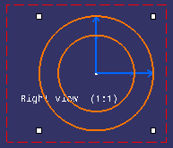
  1. From the geometry area or from the specification tree, double-click the view in which you want to instantiate the 2D component (the right view, for example).

    This view is now active.

  2. Click Instantiate 2D Component .

    Important: Double-clicking Instantiate 2D Component lets you position several 2D components on the sheet while keeping the scale and angle properties for all components.

  3. From the specification tree, click the 2D component under the detail sheet Sheet.2 (Detail) item.


    A preview of the 2D component is displayed in the view.

  4. Position the component using SmartPick then click. The Tools Palette toolbar is displayed and proposes the following commands:


    Link with detail

    Instantiate a 2D component. The component instance is linked with its reference in a detail sheet.

    Explode

    Instantiate and explode a 2D component. The component instance is not linked to its reference, so behaves as independent geometry and annotations.

    Fixed together

    Instantiate and explode a 2D component, and apply a fixed together constraint to the geometry elements.

    Important: The fix together constraint is not applied to annotations, dimensions nor dress-up elements.

    Change component origin

    Define another origin in the view.

    Change component position

    Define another position in the view.

    Change component angle

    Define the angle in the view.

    Flip component horizontally

    Rotate horizontally the 2D component instance.

    Flip component vertically

    Rotate vertically the 2D component instance.

    Angle

    Define a value for the angle.

    Scale

    Define a value for the scale.

  5. In the Tools Palette toolbar, choose your instance type. For the purpose of this scenario, check that Link with detail is activated.

  6. Click the view.

    The 2D component instance is created.

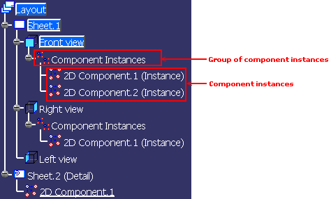
    Furthermore, the 2D component instance is added in the Component Instances node, under the appropriate view node in the specification tree.


    Important: The Component Instances node is created by default when a 2D component instance is created, but it is not displayed by default. At any time, you can specify whether or not you want to view this node in Tools > Options > Mechanical > Drafting > Display tab, Specification Tree area, by selecting 2D component instances.

  7. If needed, select the component and use the displayed manipulators to modify the component.

Note: You can easily edit the 2D component reference by right-clicking the 2D component instance, and choosing Edit Reference Component.

Important: Remember that if you selected Disable direct manipulation and/or Disable direct scaling from Tools > Options > Mechanical > Drafting > Annotation and Dress-up tab, 2D Component area, you will not be able to move and/or scale the component.