Click Swept Volume .
.
In the dialog box that appears, enter a name for the geometric
representation that will be created by the sweep.
Click Finish.
The Swept Volume dialog box appears.
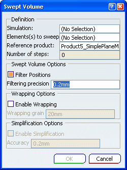
In the specification tree, select the scenario result for which you want to
compute the swept volume.
Select the parts in the model that you want to sweep.
Optional:
Select the Reference product. By default, the main product is selected in the Reference product box. The motion of the sweep
will be relative to the motion of the reference product (see VPM Volume Computation User's Guide: About swept Volumes).
Although the kinematics animation includes mechanism positions for
only discrete time increments, the volume sweep can interpolate the
positions of the mechanism between these increments to generate a
smoother shape.
- To interpolate the mechanism positions, select the Filter Positions check box, and enter the maximum distance between
positions in the Filtering precision box.
- To prevent interpolation of the mechanism positions, clear the
Filter Positions check box.
To create an envelope around the selected parts, select the Enable Wrapping check box, and enter a grain value in the Wrapping grain box.
To simplify the representation of the selected parts, select the Enable simplification check box, and enter an accuracy value.
Click OK.
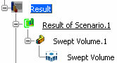
The swept volume opens in a new window. In the kinematics simulation window, Swept Volume is created under the current scenario result.
In the following example, Swept Volume.1 is the feature, and Swept Volume is the link to the geometric representation of the sweep.
To display an existing swept volume, right-click the swept volume representation in the specification tree, and select Display Representation.
The swept volume opens in a new window.
To update a swept volume, right-click the swept volume in the specification tree, and select Update.
The swept volume opens in a new window. In the kinematics simulation window, Swept Volume is updated.