Creating the mechanism | ||
| ||
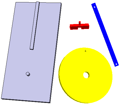
In the Assembly Design workbench, define engineering connections to position the mechanism components:
- A revolute connection between the wheel and the pin on the base; this connection attaches the wheel to the base but does not constrain its rotations.
- A prismatic connection between the slider and the track on the base; this connection attaches the slider to the base but does not constrain its position along the track.
- A revolute connection between one hole in the arm and the pin on the wheel; this connection attaches the arm to the wheel.
- A revolute connection between the other hole in the arm and the pin on the slider; this connection attaches the arm to the slider.
- A fix constraint on the base; this constraint clamps the base in place.
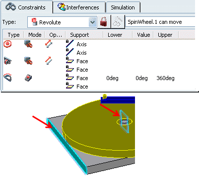
To drive the mechanism, a variable constraint must be created that defines the rotation of the wheel. Add a controlled angle constraint to the revolute connection between the wheel and the base. This constraint defines the angle between a reference plane associated with the wheel and a parallel face on the base; the initial angle is zero, but it is allowed to vary up to 360 degrees.
Click Mechanism Representation
 in the Mechanism Edition toolbar to create a mechanism representation of the product.
All engineering connections from the product are included as joints and commands in the mechanism by default.
Click Mechanism Manager
 to
review the mechanism configuration.
to
review the mechanism configuration.
The Mechanism Manager dialog box appears. The Mechanism Manager lists all of the joints in the mechanism, as well as the commands associated with each joint. Commands are enforced displacements or rotations that drive the motion of the mechanism.
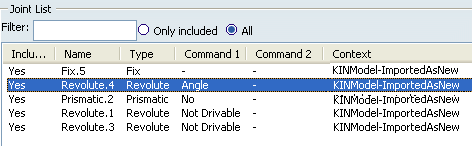
At the top of the Mechanism Manager, check the status of the degrees of freedom for the mechanism. You may need to click Update status to display the most recent status.
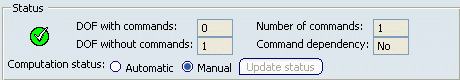
Note: When the status needs to be updated (Manual is selected), DOF, command information, and the icon status are grayed out.
Click Kinematics Simulation
 to start the simulation player.
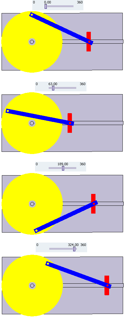
In the Kinematics Simulation player, modify the value of the command angle.
The configuration of the mechanism is updated each time you change the command angle. As the wheel rotates, the slider translates back and forth along its track.