Aligning Vertices | |||
| |||
Align Vertices on a Plane
You can project vertices onto the plane of the compass.
Click Modification
 .
.Click Alignment
 .
.
The Tools Palette is modified and new icons appear.Tip: You can also access this command by pressing CTRL+SHIFT+Q. Click Compass Definition
 to define the compass position and click the icon again when done.
Click On Plane
 .
.Note: When this option is activated the following options are available for surface selection: All Type Selection, Face Selection, Edge Selection, Vertex Selection and All Elements Selection.
Tip: In case you have clicked On Plane, you can also pick a line to project onto the plane. Select the elements to be projected.
The manipulator arrows are displayed on each axis. The manipulator is active when you are in the picking zone. You can click anywhere in the picking zone to perform a modification. As you are in the active manipulator zone, the projection plane is viewed. This plane size is defined to include all the projected points. The interactive arrows direction indicates the direction of projection and is normal to the plane.
Click the interactive arrow depending on the direction where you want to align the vertex.
The selected elements are projected onto the plane of the compass:
![]()
Align Vertices on an Axis
You can project vertices onto the axis of the compass.
Click Modification
.
Click Alignment
.
The Tools Palette is modified and new icons appear.Tip: You can also access this command by pressing CTRL+SHIFT+Q. Click Compass Definition
to define the compass position and click the icon again when done.Click On Axis
 .
.Note: When this option is activated the following options are available for surface selection: Edge Selection, Vertex Selection, All Elements Selection.
Tip: In case you have clicked On Axis, you can also pick a plane to project onto the axis. Select the elements to be projected.
Manipulator arrows are displayed on each axis. The manipulator is active when you are in the picking zone. You can click anywhere in the picking zone to perform a modification.
As you are in the picking area of the manipulator, the projection axis is viewed. This axis size is defined to include all the projected points. The interactive arrows direction indicates the direction of projection and is normal to the plane.
Click the manipulator arrow depending on the direction where you want to align the vertex.
The selected elements are projected onto the normal line of the compass:
![]()
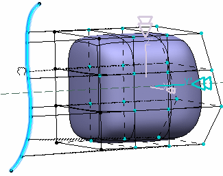
Align Vertices on a Support Element
You can project vertices orthogonally or along a defined direction onto a support element.
Click Modification
.Click Alignment
.
The Tools Palette is modified and new icons appear.Tip: You can also access this command by pressing CTRL+SHIFT+Q. Click Compass Definition
to define the compass position and click the icon again when done.Click On Body
 .
.When this option is activated the following options are available for surface selection: All Type Selection, Face Selection, Edge Selection, Vertex Selection and All Elements Selection.
Select the support element.
The manipulator is displayed with a sphere in its middle.
Move the mouse over:
- the center of the manipulator to display arrows on each axis. Click
anywhere in the picking zone to perform an orthogonal projection.
Projection traces are previewed.
- the interactive arrow corresponding to the
direction where you want to align the vertices to perform a projection along a direction.
As you can see below, it is not mandatory that the target be in the same plane as the vertices to project.
The direction of the interactive arrows indicates the direction of projection. Projection traces are previewed. The distance between the projection traces and the projection support is computed.
Note: You can click on an arrow and move the mouse towards the geometry to perform an exact aligment:
The selected elements are projected onto the support element, as shown below:
Orthogonal projection Projection along a direction
- the center of the manipulator to display arrows on each axis. Click
anywhere in the picking zone to perform an orthogonal projection.
Important:
|
| Warning: It is not possible to project two opposite edges of the same face onto a common axis. An error message is displayed. |