Creating Driving Dimensions

Driving dimensions are dimensions that drive associated geometry.

You can create the following types of driving dimensions:


  • Length
  • Distance (and distance offset in the case of two concentric circles)
  • Angle
  • Radius
  • Diameter


Before you begin:
  • Go to Tools > Options > Mechanical > Drafting > Dimension and make sure the Activate elements' analysis check-box is selected.
  • Then, click the Configure button. In the Elements' Analysis dialog box, make sure the Dimensions driving 2D geometry check-box is selected, and identify the color that will be assigned to driving dimensions (you can change it if you want).
  1. Double-click the dimension that you want to turn into a driving dimension.
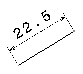


    The Dimension value dialog box is displayed.

  2. Make sure the Drive geometry check-box is selected. This dimension will now drive the geometry.

  3. In the Dimension value dialog box, modify the dimension value by specifying a new length.

  4. Click OK to validate and exit the dialog box.

    The geometry is updated according to the new driving dimension value.
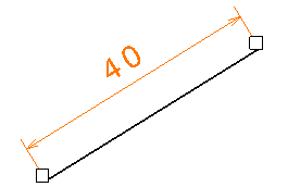


  5. Click elsewhere in the drawing to deselect the dimension.

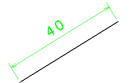
    The color defined for the Dimensions driving 2D geometry option in the Elements' Analysis dialog box is assigned to the driving dimension.


    Important:
    • Once the Drive geometry check-box is selected, you can access a contextual menu and customize the values properties according to your needs. For more information on the available options, refer to the Infrastructure User's Guide: Infrastructure and Knowledgeware: Useful Tips.
    • When a driving dimension is created between two parallel lines, then their parallelism is constrained. Therefore, if a geometrical parallelism constraint was previously applied to them, this constraint is destroyed. This avoids an overconstrained situation.

    Note: If you are a DS Passport customer, you can read the QA00000006184 article from the