Entering the Interactive Drafting Workbench

There are different ways to enter the Interactive Drafting workbench. You can choose one of them and create a new drawing representation.

Important: A drawing can be either a standalone representation or a representation aggregated to a Product. Within the Interactive Drafting workbench, you can open any drawing and work in it. However, you can create only a standalone drawing representation.

This task shows you how to:

Related Topics
About Standards

Enter the Interactive Drafting Workbench Via PLM Access > Drawing...

You can enter the Interactive Drafting workbench using PLMAccess menu.

  1. Select PLM Access > Drawing... from the menu bar. The Drawing / Representation DS dialog box is displayed.
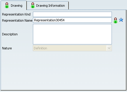


  2. In the Drawing tab, optionally specify the representation kind, enter a name for your representation, and a description. By default, a name RepresentationX (where X is a number) is specified. For more about the Drawing tab and general representation attributes, refer to the Creating an Object user task in the Infrastructure User Guide.

    Tip: Once the drawing representation is created, its attributes can be modified by selecting the drawing from the specification tree, then Edit > Properties.

  3. Click the Drawing Information tab. This tab lets you define a standard, a sheet style and an orientation for the drawing.
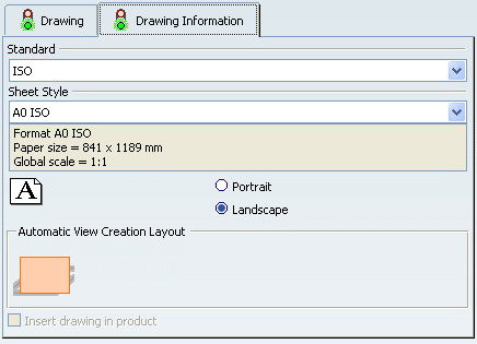
    Important: Notice the following points:
    • In the Automatic View Creation Layout area, only one choice is available and selected by default: Empty sheet. This means that the drawing representation will be created with an empty sheet.
    • The Insert drawing in product option is grayed out: you cannot insert the drawing in a product.


  4. Select a standard.

  5. Select a sheet style. The Sheet Style section displays the corresponding values for:


    • Sheet format
    • Paper size
    • Global scale

  6. Choose the orientation: Portrait or Landscape.

    Important: The last selected standard, sheet style and orientation will be used by default when creating a drawing.

  7. Click Finish. The Drafting workbench is loaded and an empty drawing representation is created. The first empty sheet, Sheet.1 is created.
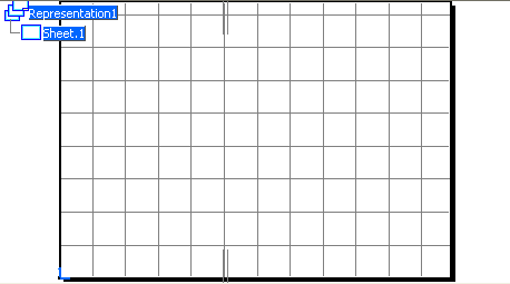
    Tip: Pressing the F3 key lets you show or hide the specification tree.


    Note: When the sheet frame is displayed in the drawing, the grid is displayed within the sheet frame. When the sheet frame is not displayed in the drawing, the grid is displayed in the entire window.

Enter the Interactive Drafting Workbench Via Start in the Bar

You can enter the Interactive Drafting workbench via Start in the bar.

  1. Click Start in the Bar , then select Mechanical > Drafting.

  2. The Drawing / Representation DS dialog box is displayed, allowing you to enter information related to your new drawing. Follow steps 2 to 6 as explained above for the PLM Access menu.