Create a Corner on Support
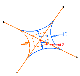
You can create a rounded corner of specified radius between two elements on the defined support.
Click Corner
 in the Wireframe toolbar (Circle-Conic sub-toolbar). in the Wireframe toolbar (Circle-Conic sub-toolbar).
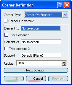
The Corner Definition dialog box appears.
In the Corner Type list, select Corner On Support.

In the Element 1 box, select a curve or a point as first reference element. In the Element 2 box, select a curve as second reference element.
The corner will be created between these two references.
In the Support box, select the surface.
The support can be a surface or a plane.The resulting corner is a curve seen as an arc of circle lying on
a support place or surface.

Enter a Radius value.
In the case of a curve as
Element 1, note that:
- all corners
have the same radius
- closed
wires can be selected
Click OK to create the corner.
The corner (identified as Corner.xxx) is added to the
specification tree.

Create a 3D Corner
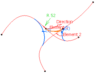
You can create a 3D corner of specified radius between two elements.
Click Corner
 . .
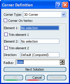
The Corner Definition dialog box appears.
In the Corner Type list, select 3D Corner.

In the Element 1 box, select a 3D curve or a point as first reference element. In the Element 2 box, select a 3D curve as second reference element.
The corner will be created between these two references.
Select an optional Direction.
The resulting corner is a 3D curve seen as an arc of circle along
the input Direction.

Enter a Radius value.
In the case of a curve as
Element 1, note that:
Click OK to create the corner.
The corner (identified as Corner.xxx) is added to the
specification tree.

Create a Corner on a Vertex
You can create a rounded corner of specified radius on vertex.
- Select the Corner On Vertex option to create a corner by
selecting, as Element 1 (Element 2 is grayed out):

Trim Elements
You can trim the elements.
|