Managing the Background Visualization | |||
| |||
Select a plane.
A Work on Support is automatically created. If a Work on Support already exists in the same plane, it is activated.
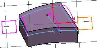
Important: - You can also select a set of elements (for instance two lines) belonging to the same plane in order to determine a plane. If the elements are in different planes, an error message is issued. Note that multi-selection is only available before entering the command.
- You can also select an annotation text that will be used to determine a plane.
Click Pickable visible background
 to deselect it.
The Work on Support is removed from the specification tree, if it is automatically created and if there are no geometries created on this Work on Support.
Click No 3D background
 and a join feature.
 All geometric elements available in the plane of the join feature are visible. All the other elements are invisible.
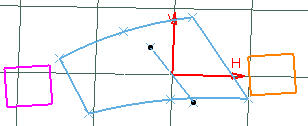
Click Unpickable background
 .
.
You can only pick the geometric elements that are in this plane.
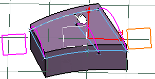
Other elements cannot be picked:
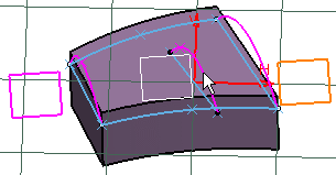
Click Low intensity background
 .
.Geometric elements that are in the plane are displayed normally. However, elements that are not in the plane are displayed with a low intensity (including curves and wireframe elements) but they still can be picked:
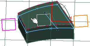
Click Unpickable low intensity background
 .
.Geometric elements that are not in the plane are displayed with a low intensity and they cannot be picked:
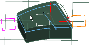
Click Lock current view point
 .
.Now, you can only perform translations in the plane parallel to the screen and rotations along the axis normal to the screen as well as zoom in and zoom out. Note that you must use the mouse to perform these transformations when the current view point is locked.
Important: - Low intensity elements (that are not in the plane) are not displayed in front the plane geometry but behind, even though they are geometrically in front of it.
- The status (active/inactive) of all the above commands are retained when changing workbench.
- Visualization modes are temporary, they only act as filters in the 3D area. They disappear once the command is deactivated.