Creating an Automatic Fillet | |||||
|
| ||||
Click Automatic filleting
 in the Advanced Operations
toolbar.
in the Advanced Operations
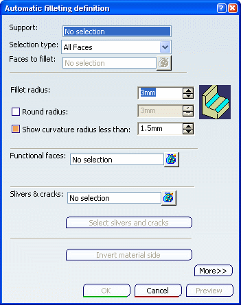
toolbar.The Automatic filleting definition dialog box appears.

Select a support surface in the Support box to manage the feature which is to be filleted.
This box becomes grayed out if the Faces to fillet, Functional faces or Slivers & cracks box is selected. By removing all specified faces, it becomes selectable again.
Select the computation mode from the Selection type drop-down list:
-
All Faces (default mode), as in our scenario: edges around all the faces of the support are filleted. In this mode, the Faces to fillet box is disabled.
-
Faces selection: the edges around the faces selected are filleted.
-
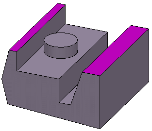
Optional: If you do not want to fillet the whole edges of the surface, select the faces which you do not want to fillet in the Functional faces box. The selected faces turn purple, indicating that they will not be filleted:

Important: In case you want to fillet the whole edges of the surface, you just need to adjust the radius value according to your needs and run the capability. Define the radius value you want to assign to the concave edges in the Fillet radius box.
Select the Round Radius option and define a radius to round convex edges.
The icon on the right side of the box is modified accordingly.
Select the Show curvature less than option to ensure that the application displays the fillets whose radius value is less than the smaller radius value you entered in the box. In case the application generates fillets whose radius value is less than defined value, a warning message will therefore be issued.
Click Invert material side to reverse the orientation of the virtual material side. In this case, concave edges become convex and convex edges become concave.
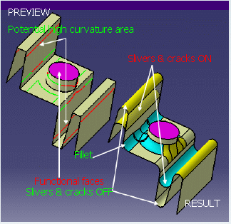
Tip: You can also click on the red arrow in the 3D area. Warning: This button only becomes available when the Round Radius option is selected. Optional: Click More>> to expand the dialog box and display images helping you define your specifications:

Click OK.
The progress bar appears. In case you want to interrupt the operation, just click Cancel.

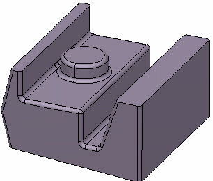
The operation is complete. The new feature (identified as AutoFillet.xxx) is added to the specification tree. All the edges except for edges surrounding both functional surfaces are filleted:
