Creating Imports

You can create imports. The Create Imports command helps to have an accurate control of the destination of the import elements you create.


Before you begin: Activate the representation where the import is to be created.
Related Topics
More about the Import Creation Command
  1. Select Insert > Create Import... .

    The Create Import dialog box appears.

    Warning: The command is exclusive. It allows preselection but not multi-selection.

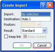
  2. In the Import box, select the object from which you want the external and internal references to be created.

    Note: The supported elements are:

    • wireframe and surface features
    • volumes
    • sketches
    • bodies
    • parameters (if they are set as visible in Tools > Options)
    • sub-elements (face, edge, vertex)
    • solid functional sets (SFS)
    • functional specifications
    • functional sets.

    The last three elements are only available with the Functional Modeling Part workbench.

    The name of the object appears in the Import box.

  3. In the Destination box, select the destination to aggregate the import to be created.

    By default, the destination is the in work object.

  4. In the Position list, select the position of the import to be created relative to the destination:

    • After: the element is positioned after the reference.
    • Before: the element is positioned before the reference.
    • Inside: the element is positioned inside the reference.

    The element will be imported in the place you selected.

    Note:

    • The list only presents choices that are possible.
    • The default value is After (when the choice is possible).

  5. In the Result list, select the kind of result you want to have after the duplication.

    Important: The list updates according to the type of feature you want to import.

    Note: Indeed, some features have more than one geometrical result. For instance, a sheetmetal body can have a form result and a flat result.

  6. Select the type of associativity:

    • Not associative with the initial selected element: clear the Keep link option.

      Note: If the box is cleared, a datum feature without link is created.

      Warning: If the box was initially selected and then cleared, it is possible that no object is created (because of multi-context cycle). In this case, nothing is done at this step but an error message appears when validating.
    • Associative, including in position, (meaningful for Assembly Design only): the Keep link and Keep context options are activated.

      Important: By default, for associative imports, the associativity mode is in shape and position. Therefore the Keep context option is available only when Keep Link is selected.
    • Associative (in terms of geometrical shape but not in position): the Keep link option is activated.

    Important: By selecting the options you can switch to an associative import that is only associative in terms of geometrical shape but not in position.

  7. Click OK when satisfied.


    • The created imports are inserted in the specification tree.
    • The solid external references are created in a solid body or a body according to the option Enable hybrid Design defined in Tools > Options > Infrastructure > 3D Shape Infrastructure > 3D Shape tab.

Important: For internal import, the default state of the feature pasted with the As Result with Link option is unfrozen. In this state, the copied geometry is synchronized with its source. You can freeze imports. When elements are imported using multi-part links (external references) or using the Copy-Paste As result with link capability, the deactivation concerns the link, not the feature. As a consequence, the feature can still be selected. For more information about freezing links, refer to Part Design User’s Guide: Freezing Links.