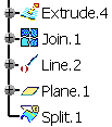
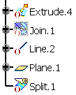
Right-click the element to be deactivated from the
specification tree, and select xxx object > Deactivate. Click OK.
The selected element as well as its children and aggregated
elements (if any and depending on the selected options) are
deactivated.
The ( ) symbol is displayed in
the specification tree, and the corresponding geometry is
hidden. For more information, refer to Part Design User's Guide: Interface Description: Masks.
- If the selected element does not have any children nor any aggregated
elements (for instance Line.2), it is directly deactivated. This is
indicated by the ( ) symbol in the
specification tree:

- For all the other cases, the Deactivate dialog box appears
and the geometry to be deactivated is highlighted.
- The selected element has children but no aggregated elements.


-
The Deactivate all children option is selected: it lets you
deactivate the geometry based upon the element to be deactivated,
that is dependent elements. By default, the option is selected, except for modification features
when a reroute is possible (see example below). If you clear the option, a warning icon is displayed to inform you that
there will be an update error.

-
The
Deactivate aggregated elements option is disabled.
- The selected element has aggregated elements but no children
(for instance a Part Design feature based on a sketch).


- The Deactivate all children option is disabled.
-
The Deactivate aggregated elements
option is enabled: it lets you deactivate the geometry aggregated below
the element to be deactivated. Whenever you deactivate a feature, you can choose between deactivating
the corresponding aggregated element or not (as shown below):

When deactivating a Boolean operation, by default all operated bodies
(located below the Boolean operation node) are deactivated too: just
clear the Deactivate aggregated elements check box if you
want to keep the bodies.
|


 to display the list of elements.