More about Masks | ||||||
|
| |||||
Mask Visualization
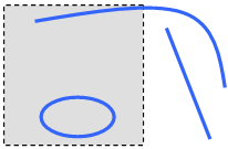
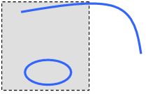
You can visualize the mask in the current view.
The creation of the mask takes into account the size of the viewer and a depth enabling to contain the geometries displayed on the screen. The depth of the box corresponds to the smallest dimension allowing the selection of the all elements visualized in the current view. The mask is always oriented with the main direction of the axis system support. It is the biggest box, oriented with the axis system, that can include the geometries displayed on the screen.
![]()
Current Masks
You can activate the default current mask.
The mask is created in the current part and is displayed under the
Masks feature in the specification tree. By default, the last
created mask is displayed in red in the specification tree.
Only masks that are associated with the current axis system can be
activated. If the selected axis system is linked to several masks,
the latter are displayed under the "Linked to current axis system"
node in the specification tree.
Use the Set As Current/Set As Not Current
contextual menu on the mask feature to define the default current
mask. The former active mask is inactivated.

Important:
|
![]()
Mask Activation / Deactivation
You can either activate or deactivate the mask.
- The created mask is associated with the current axis system, but you can select another one. If you change the current axis system, the active mask becomes inactive.
- If the current axis system is the support of the created mask, you can choose to automatically activate it or not. If it is not the current one, the mask is created but inactivated.
- If you delete the active mask, all remaining masks are inactive and all elements are displayed. If you delete an inactive mask and an active mask exists, the latter remains active. If you delete the axis system that is linked to several masks, the latter are automatically deleted and a warning dialog box is issued.
- Several masks can be specified in a representation but there can be only one active mask. If there are several masks and you activate one, the former activated mask is automatically deactivated. By passing the pointer over an inactivate mask in the specification tree, it is pre-highlighted but the geometry is not displayed. If you click on the inactive mask, it is highlighted and the geometry is displayed. In both cases, the active mask remains active.


![]()
Datum Masks
You can create masks using the Datum mode.
You can select the Coordinates type and select two datum points. The link between the axis system and the mask remains but there is no associative link between the input points and the mask.
The icon in the specification tree looks like this: ![]() .
.
![]()
Isolated Masks
You can use the Isolate contextual command in order to break the associative link between the input points and the mask.
The mask is now considered as a datum mask (see above). Therefore, the link between the axis system and the mask remains.
![]()
Miscellaneous
Here is some information you need to know about mask.
- When you create a new mask in the representation, you cannot select an axis system of another representation. Moreover, you cannot activate a mask in an inactive representation
- You can edit a mask and modify all its parameters, except for the axis system.
- In case you are working in a product environment, and providing there are several parts, you can only see the mask whose part is active. If the product is active, masks cannot be applied.
- The geometry that is completely outside the box is not displayed in the No Show area. However, it can still be picked from the specification tree.
- Sketches are considered as one feature.
- If all the vertices of a surface or a wire are located outside the mask box, the geometry is not displayed even if some geometry passes through the mask box.