More about Ordered Geometrical Sets | ||||
|
| |||
Visualization of Features
You can visualize the features in the specification tree. Note that when opening a document, features are visualized depending on their order in the specification tree. After a modification, the order is no longer respected; therefore the visualization may be different.
-
Only features that come before the current object and that are not
absorbed by any feature preceding the current object are visualized
in the specification tree.
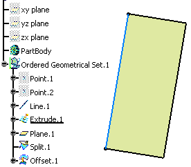
It can be useful to temporarily see its future geometry. To do so, you can check the Geometry located after the current feature option in Tools > Options > Infrastructure > Part Infrastructure > Display tab. It allows you to also display the geometry located after the current feature.
-
A color assigned to a feature is propagated to all the features
that successively modify this feature and so on.
This is why it is possible to set a specific color only on creation
features.
Therefore, changing the color of a modification feature modifies
the color of the initial state.
Here Extrude.1 is absorbed by Split.1. Therefore the color of Extrude.1 is propagated onto Split.1.
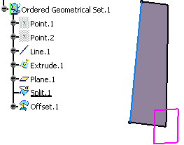
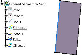
| Important: The same behavior applies on Show/No show attributes. |
![]()
Selection of Visualization of Features
The selection of features located after the current feature or absorbed features is not possible.
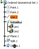
Here, for instance, when editing Extrude.1, the selection of Offset.1 is not possible because Offset.1 is located after Extrude.1 which is the current object. A black sign indicates that this selection is not possible. Additionally, the application displays a tooltip explaining why it is not possible.
To ensure the consistency between the visualization in the 3D geometry and the selection in the specification tree, features that cannot be visualized in the 3D geometry cannot either be selected in the specification tree.
![]()
In work and Current Features
You can set any feature as current by defining it as In Work object. Unlike features within a geometrical set, features in an ordered geometrical set can be set as current: a given step of the design creation is chosen and what is located after it is neither accessible nor visible. The next created element is created after the In Work object. If the new feature to be inserted is a modification feature, features after the In Work object may be rerouted to the new created feature.
![]()
Insertion and Deletion
You can insert or delete the features in the ordered geometrical sets. Inside an ordered geometrical set, the Insert and Delete commands may have impacts that result in replace actions based on absorption rules.
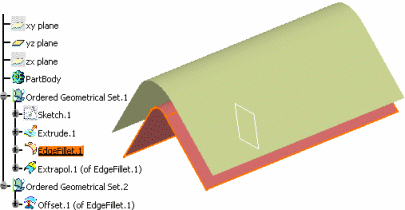
Here, the edge fillet (Edge Fillet.1) is the current object.
A split feature (Split.1) is inserted just after EdgeFillet.1. This new feature absorbs EdgeFillet.1 and therefore the latter is no more displayed.
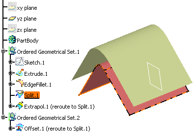
To ensure the ordering rule, the links to the absorbed feature (EdgeFillet.1) must be rerouted to the inserted feature (Split.1). This replacement applies to all the features inside the root ordered geometrical set (Ordered Geometrical Set.1) located after the inserted feature and to all the features located inside other ordered geometrical sets roots.
This replace action may not be applicable; in this case a warning message is issued.
Using our example, had we selected the other side of Split.1, the replacement of the edge to extrapolate (defined in Extrapol.1 feature) would not have been possible.
As a consequence of the replace action, the affected features (that is Extrapol.1) become "not updated". The update following the insertion may also produce an error and in this case the design will have to be modified so that the inserted feature is compatible with the entire design.
The replace actions performed by the Delete command are generally the opposite of the replace actions performed by Insert command. Using our example, deleting Split.1 leads to the replacement of Split.1 by EdgeFillet.1. Nevertheless, bear in mind that deleting a feature can lead to a configuration different from the one preceding the insertion of a feature (for instance, if inserting a Trim feature, all inputs will be replaced by this feature but if deleting it, the Trim feature will be replaced by its main input).
Based on this mechanism stand two methodologies for:
- multiple references to an intermediate state of design inside an ordered geometrical set,
- external links to the "end design" specified inside an ordered geometrical set.
Multiple References
Inside a root ordered geometrical set, a feature can be the input of several features (all creation features, except for the last feature, according to the order in the specification tree, which can be a modification feature). In some cases, the design may require to create several modification states of a same feature. To do so, it is necessary to create copies (Copy/Paste As Result With Link).
This example shows how to allow multiple modifications of EdgeFillet.1 feature, considered as an "intermediate state of design". A copy of the feature is inserted just after it. In the beginning of every sub-set where this state of design will be used, a copy of the copy is created.
Using this construction, modifications applied to EdgeFillet.1 or to the copies of the copy will affect only the design in Sub OGS.1.
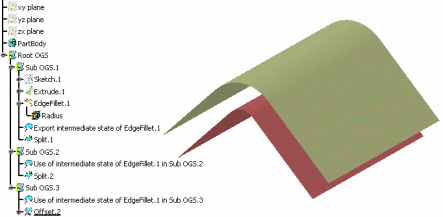
External Links
You can manage the external links between an external element from the document and a feature inside an ordered geometrical set. The replace actions due to design modifications (insertion and deletion) do not affect external links (that is the links between an external element from the document and a feature inside an ordered geometrical set). To ensure that the links will always reference the last state of design, it is necessary to create a copy (Copy/Paste As Result With Link) of the last current feature in a new ordered geometrical set. This copy can possibly be published. As a consequence, the external link will have to reference this copy or its publication.
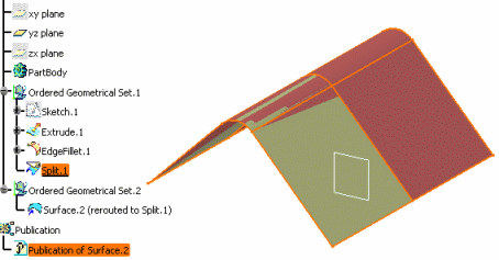
In this example, Surface.2 is a copy of EdgeFillet.1. The external link has to reference Surface.2 or its publication.
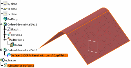
A split feature is inserted after EdgeFillet.1. As a consequence, Surface.2 is rerouted to Split.1 and so is the external link.
| Important: When copying/pasting As Result an ordered geometrical set, absorbed features are not pasted. However, if you select the features to be copied/pasted As Result within the ordered geometrical set, both absorbed and non absorbed features will all be pasted. |