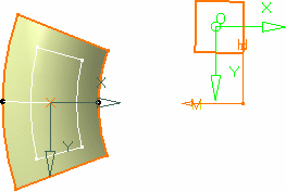
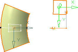
More about the Develop Command | ||||
|
| |||
Developing Modes
There are three developing modes. The difference between these three modes deals with the way the points are mapped onto the revolution surface.
The following illustration shows the three developing types, based on developing the black solid wire, the two black dotted wires representing the 1 and 2 coordinate lengths in the wire's axis-system.
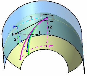
As you can see, the results differ slightly, the developed curves not ending on the same point.
Develop-Develop
A given point (p) of the wire is developed on the revolution surface by mapping its first coordinate as a curvilinear abscissa on the revolution surface (1 into 1') up to a (p') point (represented by the light blue dotted curve), then from that (p') point reporting the other coordinate of (p) as a curvilinear abscissa (2 into 2') along the revolution surface (dark blue dotted curve). The resulting developed wire is the dark blue solid curve in the above illustration.
Develop-Project
A given point (p) of the wire is developed on the revolution surface by mapping its first coordinate as a curvilinear abscissa (1 into 1') onto a virtual cylinder passing through the point on support (default or user-defined), to generate a (p') point (represented by the light blue dotted curve), reporting the other coordinate parallel to the cylinder's revolution axis, then projecting normally from that cylinder onto the revolution surface (light green dotted line). The resulting developed wire is the light green solid curve in the above illustration.
Develop-Develop inverted
A given point (p) of the wire is developed along the revolution surface by mapping its first coordinate as a curvilinear abscissa on the virtual cylinder up to a (p'') point (represented by the pink dotted line), then from that (p'') point reporting the other coordinate of (p) as a curvilinear abscissa along the revolution surface. The resulting developed wire is the pink solid curve in the above illustration.
![]()
Development Optional Parameters
Three optional parameters are available from the Develop Definition dialog box allowing to apply a transformation to the wire prior to developing it.
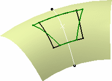
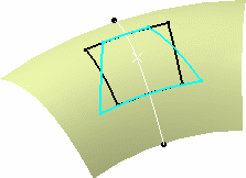
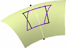
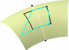
They are illustrated below by the developing of a square wire onto a surface:
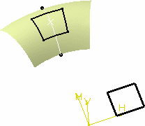
Radiantness
It allows to specify a radial deformation ratio on the developed wire. This transformation is defined by the distance between the axis-system origin on the revolution surface and the revolution axis ®), and the ratio you specify in the Develop Definition dialog box.
The formulas used to define the radiantness are:
x' = ® + y1 * Ratio) * x1 / ® + y1)
y' = y1
where
x1 and y1 are the coordinates of any point in the initial axis system of the wire to be developed
x' and y' are the coordinates the same point on the developed wire
Inclination
It corresponds to the angular deviation (d) from the default developing. The formulas used to define the inclination are:
x' = x1 + y1 tan(d)
y' = y1
You can combine these two options to develop a wire
Intermediate Radius
A ratio is applied to the wire's coordinates along the y axis, prior to developing it (i.e. the development operation itself is not affected, only the wire's shape is modified along y before the development).
