Click
Aligned Section View/Section Cut
 .
.
The
Aligned View Creation dialog box appears.
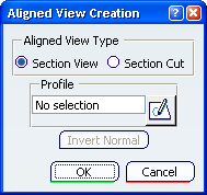
Specify the type of view that you want to create:
Section View or
Section Cut. For the purpose of this scenario,
select
Section View.
Click
Sketch
 to sketch a new profile that will be used as cutting plane.
Select a planar surface.
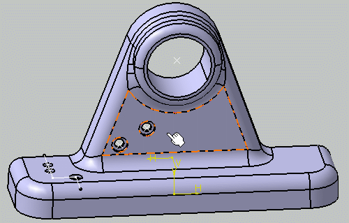
The application switches to the Sketcher workbench to let
you sketch the cutting profile.
Click
Profile

Sketch your cutting profile as shown here.
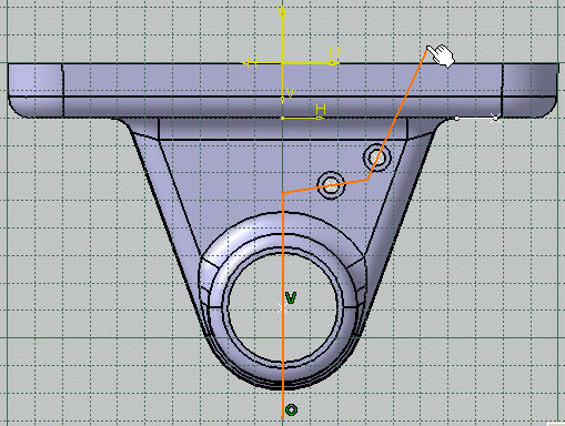
You can constrain the sketch lines in order to ensure their
position according to some features of the part.
When you are done, click the
Exit workbench
 to exit the Sketcher workbench.
The newly created sketch is now selected in the
Profile field of the
Aligned View Creation dialog box.
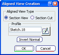
Click
OK.
The aligned section view is now created and listed in the
specification tree; it cannot be activated. It is made up of three distinct
section views/annotation planes, each of which can be activated and behaves
like a regular section view/annotation plane. Each view is associative to the
sketched line that defines it.
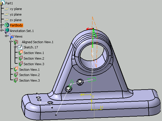
You can now start creating annotations in each section view of the
aligned section view. If you then extract the aligned section view to 2D in the
Generative Drafting workbench, all the annotations defined in each component
view will be generated.
Optionally, right-click
Aligned Section View.1 in the specification
tree and select
Invert Normal in the contextual menu if you
want to invert the normal of the aligned section view: this actually inverts
the normal of all the section views/annotation planes that make up the aligned
section view.