Displaying Geometric Information On Elements | |||||
|
| ||||
Click Geometric Information
 in the Generic Tools toolbar.
The Geometric Analysis dialog box appears.
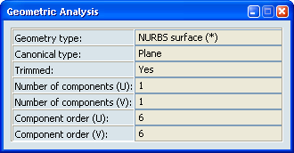
The following information is displayed in the dialog box:- The element type.
- The canonical type.
- Whether the element has been trimmed, or not.
- The number of segments (components) in both U and V directions (where applicable).
- The order of the element in both U and V directions (where applicable).
In addition, a vector representing the element's orientation (U for a curve, and U and V for a surface) is displayed on the geometrical element.
Notes:
- A 3D curve created using the Control Points type will show a maximum order of 6.
- For sweep features, the displayed geometry type will be the one of the included surface (e.g. NurbsSurface).
- For elements whose type is either NurbsCurve, PNurbs or NurbsSurface, a (*) will be appended to the displayed type when the element is not rational, i.e., a polynomial one.
- Canonical type will be Unknown when it is not possible to determine it (for example; multiple surfaces or parts).
When you have finished, do one of the following:
- Click Geometric Information
to exit the command.
- Close the dialog box.
- Click Geometric Information