Create a Styling Fillet
How to create a styling fillet between two surfaces using the the Styling Fillet command.
Click
Styling Fillet
 . .
The
Styling Fillet dialog box is displayed.
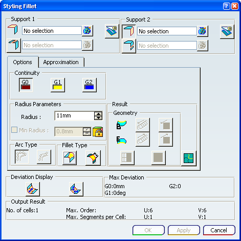
Under the Options tab of the dialog box: - In the Continuity area, select G0
 continuity. continuity.
- In the Fillet Type area, unselect Variable Radius
 . .
Select two surfaces.
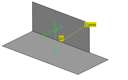
Input surfaces can be intersecting or non-intersecting. In case of non-intersecting surfaces, specify the edges of the input surfaces to extrapolate so that they intersect. A message is displayed asking you to give the input edges for extrapolation. The input edges must be the border edge of the input surface and must be G1 continuous. If the edges are not G1 continuous then an error message is displayed. When the given input edges for extrapolation fail to find an intersection between the given set of input surfaces, an error message is displayed. Two vector arrows, the G0 continuity symbol and a radius value appear.
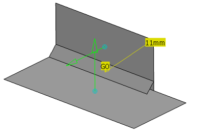
Click Apply A G0 fillet appears.
Select
G2
 continuity continuity
- The G2 continuity symbol appears.
- The fillet color changes to red indicating that it does not represent the current selections in the dialog box.
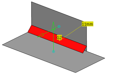
Click Apply A G2 fillet appears.
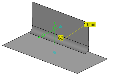
Adjust the fillet radius to vary linearly along the length of the fillet: - In the Fillet Type area, select Variable Radius
 . . A manipulator with a radius value appears at each end of the fillet.
- Click one of the radius values, adjust its value in the Edit dialog box and then click OK.
The fillet color changes to red indicating that it does not represent the current selections in the dialog box.
- Click Apply.
The variable radius fillet appears. The radius varies linearly from one end of the fillet to the other.
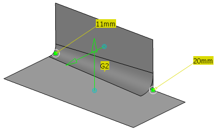
Adjust the fillet radius to vary non-linearly along the length of the fillet: - Drag one manipulator towards the center of the fillet.
This creates an additional manipulator and its radius value.
- You can create as many of these additional manipulators as necessary.
- To remove an additional manipulator, drag it to the end of the fillet.
- The two end manipulators cannot be moved.
- Two additional manipulators cannot be created at the
same position.
- Adjust the radius value of this new manipulator.
The fillet color changes to red indicating that it does not represent the current selections in the dialog box.
- Click Apply.
The variable radius fillet appears. The radius varies non-linearly from one end of the fillet to the other.
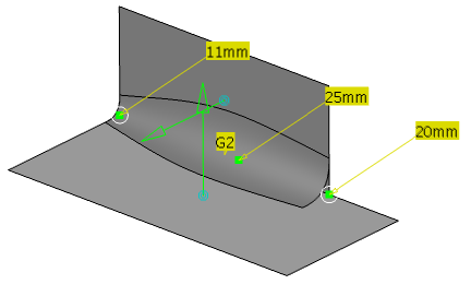
When you have finished, click
OK.
A Styling Fillet is created in the specification tree under the PartBody.

Manage Multiple Results in Fillet
You can handle multiple results after the filleting operation. The Multi-Result Management allows you to keep either one or all sub-elements created.
Click
Styling Fillet
 . . Select the two input surfaces.
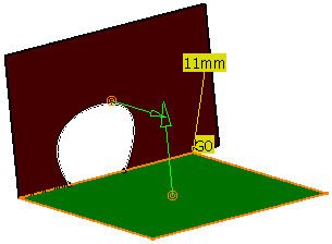
Click OK in Styling Fillet dialog box. The Multi-Result Management dialog box is displayed.
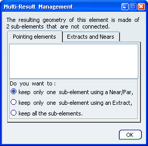
The following options are available:
- keep only one sub-element using a Near/Far allows you to keep only one sub-element by selecting a reference element and choosing the nearest/furthest sub-element from this reference element. The Near/Far Definition dialog box is displayed allowing you to make this selection.
- keep only one sub-element using an Extract allows you to keep only one sub-element by selecting an extract of the element. The Extract Definition dialog box is displayed.
- keep all the sub-elements allows you to keep all the sub-elements created.
For more information about Multi-Result Management, see Generative Shape Design : Tools : Managing Multi-Result Operations Select keep all the sub-elements option. When you have finished, click
OK. All the created fillets are kept.
|