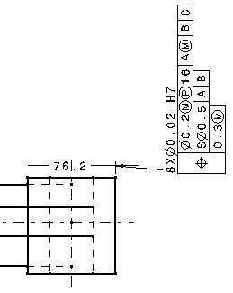
Specify leader orientation
You can orient the geometrical tolerance leader perpendicularly to the
element to which it is associated (for example, if the leader is associated
to a dimension, you can position the leader parallel to the dimension line
and orthogonal to the extension line).
For this, you have two different possibilities:
- Either go to Tools > Options > Mechanical > Drafting
> Annotation and Dress-up tab and check Snap by default (SHIFT
toggles). Then, click the Configure button and select
either On orientation or Both. To orient
directly the geometrical tolerance leader perpendicularly to the associated
element, press the Shift key before clicking in the drawing
to position the tolerance .
- Or go to Tools > Options > Mechanical > Drafting > Annotation
and Dress-up tab and check Geometrical tolerance in
Annotation Creation. The leader will be oriented perpendicularly
to the geometry by default. In this case, pressing the Shift
key will let you orient it differently.
