Adding a 3D Clipping to an Exact View | |||||
|
| ||||
Click Add 3D Clipping
 in the Views toolbar
(Break view sub-toolbar).
The Clipping Object dialog box
appears with a 3D viewer.
in the Views toolbar
(Break view sub-toolbar).
The Clipping Object dialog box
appears with a 3D viewer.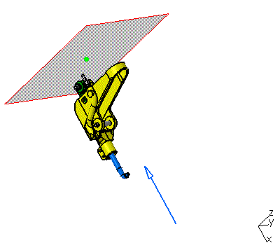
It contains the following options:
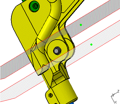
Clipping Mode: elements intersecting the clipping planes will be cut.
-
Clipping Box: to select 3D elements inside the clipping box.
-
Clipping By Slice: to select 3D elements between the back clipping plane and the front clipping plane.
-
Back Clipping Plane: to select 3D elements positioned ahead of the plane. The blue arrow indicates the front face of the clipping plane. By default, this clipping mode is selected.
User Input: to define the position and dimension of the clipping planes.
Tip: To modify the position of a clipping plane, you can also drag and drop the green bullet positioned at its center. -
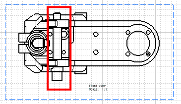
Select the Clipping By Slice clipping mode, and enter the User Input described below. You can also drag and drop the green bullets to position the clipping planes in the 3D viewer.
Click Create. The front view is modified and the dialog box is closed.
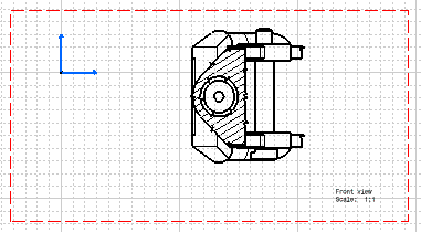
The background and foreground of the cylinder are now removed.