Creating Geometrical Tolerances | ||||||||
|
| |||||||
Select the face as shown.
Note: This scenario illustrates the creation of a geometrical tolerance by selecting geometry, but you can also select any Part Design or Generative Shape Design feature in the specification tree. In this case, the created annotation will not be attached to the selected feature, but to its geometrical elements at the highest level.
The Geometrical Tolerance dialog box appears.
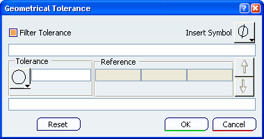
This dialog box allows you to:
- Specify as many specification lines as you want (with the Up and Down arrows).
- Insert several modifiers anywhere in a tolerance or a reference.
- Add notes upper and lower the set of specification.
In the Geometrical Tolerance dialog box:
- Select the Parallelism symbol to define the tolerance.
- Enter the value of the tolerance: 0.5 and insert the Least Material Condition symbol modifier.
- Enter A as reference.
- Specify the upper note and lower note texts.
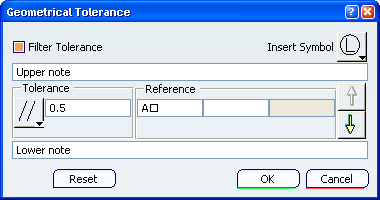
Important: Modifiers are not displaying in tolerance and reference fields and appear with a special character according to the font.
Click OK to confirm the operation and close the dialog box.
The geometrical tolerancing annotation is attached to the part.
The geometrical tolerance entity (identified as Geometrical Tolerance.xxx) is added to the specification tree in the Geometrical Tolerances group.