Analyzing Draft Angle | |||
| |||
Click Draft Analysis
 in the Shape Analysis toolbar.
The Draft Analysis dialog box is displayed.
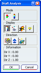
Set up your analysis:
- In the Mode area of the dialog box, select Quick Analysis Mode
 .
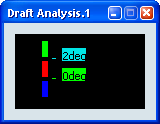
. - In the Display area of the dialog box, select Show/Hide color scale
 .
.The Draft Analysis.x dialog box is displayed. It shows the color scale and identifies the corresponding values for the analysis.
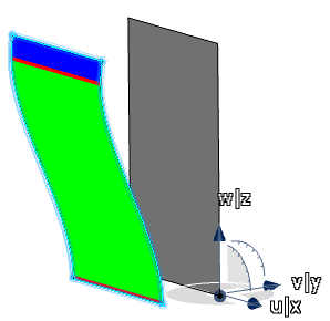
- In the Mode area of the dialog box, select Quick Analysis Mode
Select a surface for analysis.
The quick analysis is displayed on the surface.
The draft direction is the w/z axis of the compass.
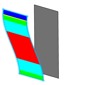
In the Mode area of the dialog box, select Full Analysis Mode
 .
.The color scale and range of values in the Draft Analysis.x dialog box are expanded.
The corresponding colors are displayed on the surface.
In the Display area of the dialog box, select On the Fly
 and move the pointer over the surface.
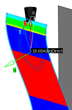
The following information about the current pointer location is displayed:
- Green arrow, N: The normal to the surface
- Red arrow, D: The draft direction
- Blue arrow, T: The tangent to the surface
- Circles: The plane tangent to the surface
- Value (reverse highlighted): The angle between the draft direction and the tangent to the surface (the value is expressed in the units set in Tools > Options > General > Parameters > Units tab)
- The cone
- Value (unhighlighted): The cone angle (the angle between the axis of the cone and the draft direction D)
As you move the pointer over the surface, this information is updated dynamically.
Warning: The On the Fly analysis can only be performed on the elements of the current part. Note that you can activate the On the fly option even when not visualizing the materials. It gives you the tangent plane and the deviation value.
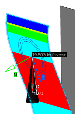
Click Inverse
 to reverse the draft direction.
This command affects all selected elements.
Important: - If a result is obviously inconsistent,
click Inverse
to locally invert the draft direction.
- The pulling direction defined in a Part Design's
Draft is not taken into account. In case of inconsistency with the draft analysis
orientation, click Inverse
.
- If a result is obviously inconsistent,
click Inverse
Right-click the cone angle to display the Angle Tuner dialog box and then modify the angle using the up/down arrows.
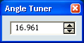
The value is automatically updated in the color scale dialog box, on the geometry and the cone diameter is adjusted.
The value in the color scale dialog box (16.961deg in the example shown below) is highlighted in a different color .
Important: You cannot modify the angle below the minimum value or above the maximum value. 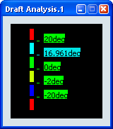
Define a new draft direction and then lock the direction:
- In the Draft Analysis dialog box, click Compass
 .
.The compass is placed in the 3D area.
- In the Draft Analysis dialog box, click Lock draft direction
 .
.The draft direction (D, red arrow) is locked in the new direction. If you make subsequent adjustments to the compass, the draft direction will remain unchanged.
- In the Draft Analysis dialog box, click Compass
Note:
- Note that settings are saved when exiting the command,
and redisplayed when you select Draft Analysis again.
- Be careful, when selecting the direction, not to deselect the analyzed element.
- A draft analysis can be performed just as well on a set of surfaces.
- If an element belongs to an analysis, it cannot be selected simultaneously for another analysis; you need to remove the current analysis by deselecting the element to be able to use it again.
- In some cases, even though the rendering style is properly set, it may happen that the analysis results are not visible. Check that the geometry is up-to-date, or perform an update on the involved geometric elements.
- The analysis results depend of the current object. May you want to change the scope of analysis, use the Define in Work object contextual command.