In the Shape Analysis toolbar, click Cutting Plane Analysis
 .
.
The Cutting Plane Analysis dialog box appears and a reference plane is displayed in the 3D area.
Select one or several elements by doing one of the following:
- To select a single element:
- Click the element in the 3D area or in the specification tree.
- To select multiple elements using Ctrl-click:
- Ctrl-click each of the elements in the 3D area or in the specification tree.
- When finished, press F8.
- To select multiple elements using the Elements / Objects dialog box:
- Click
 next to the Elements / Objects selection box.
 The dialog box opens.
- Click the elements in the 3D area or in the specification tree to add them to the list in the dialog box.
- If necessary, Remove or Replace elements.
- When finished, click Close.
The element name or the number of selected elements is shown in the Elements / Objects selection box.
Create some cutting planes parallel to the reference plane:
- In the Sections Type area, click Parallel planes
 .
.
- In the Number/Step area select the Number option and increase the value to 10.
Curves representing the cutting planes are projected onto the selected elements. The
curves are in the same plane as the reference plane.
In the example shown, both elements are selected.
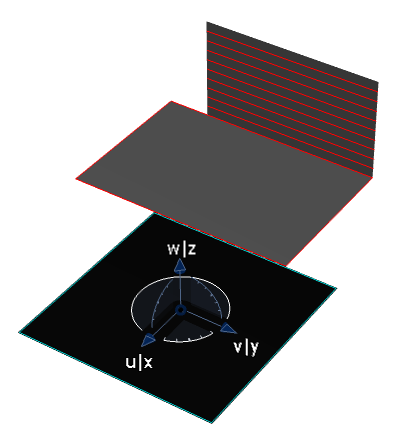
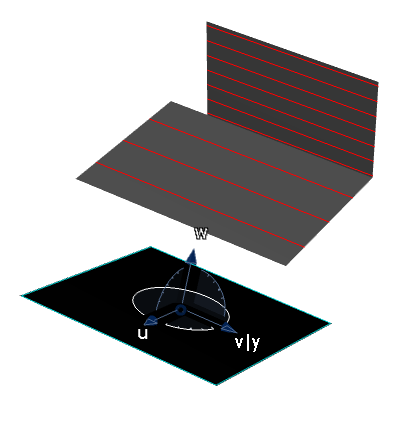
Drag one of the arcs of the compass.
The curves representing the cutting planes are updated on the selected elements.
Create some cutting planes perpendicular to a curve:
- In the Sections Type area, click Planes perpendicular
to curves
 .
.
- Click in the Curves selection box and then select a curve.
- In the Display area, select Planes.
Reference planes appear on the curve. Curves representing the cutting planes are projected onto the selected elements. The
curves are perpendicular to the curve and aligned with the reference planes on the curve.
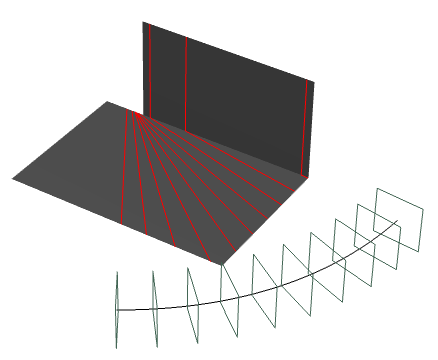
In the Number/Step area, select the On Curve option and drag the reference plane along the curve.
A curve representing the cutting plane is swept across the selected elements.
You can create several planes: right-click the reference
plane and select Keep this plane from the contextual
menu.
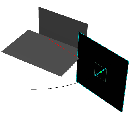
Adjust the boundaries of the cutting plane curves:
- In the Sections Type area, click Parallel planes
 .
.
Curves representing the cutting planes are projected onto the selected elements.
The
curves are spread evenly across the selected elements.
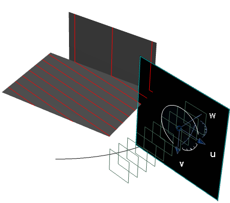
- In the Boundaries area, select the Manual
option and adjust the values of Start and End.
The boundaries of the curves projected onto the selected elements move accordingly.
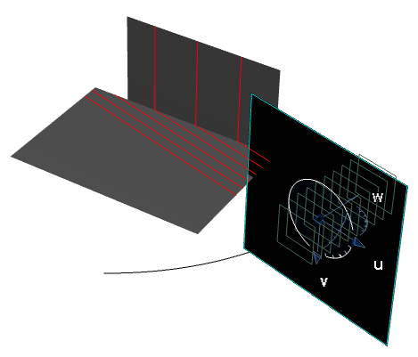
Use the cutting plane curves to create a curvature analysis of the selected elements:
- In the Display area, select Curvature.
- Click Settings and adjust the settings in the Porcupine Curvature dialog box as necessary.
- Click OK in the Porcupine Curvature dialog box when you are satisfied with the result.
Porcupine curves are created on each cutting plane on the selected elements.
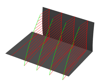
Note:
The Project on Plane
option is implicit, meaning that a curvature analysis
signature is applied due to its projection on the cutting
plane.
The result is similar to using the Porcupine Curvature Analysis command,
except that it displays spikes for each intersection curve.
When you have finished working with this command, do one of the following:
- To create the analysis, click OK.
The analysis is added to the specification tree where it is identified as Command_Name.Analysis.x.
The analysis will be updated automatically whenever you modify any of the elements in the analysis (for example when you deform an element using control points).
- To abandon the analysis, click Cancel.


