Visualizing Fasteners | |||
| |||
Visualize the K Vector and 3D Point
You can use this mode to visualize the K vector and the associated 3D point in the 3D area.
Click K Vector visualization
 .
.
The K Vector Visualization dialog box is displayed. It displays the list of selected fasteners and the grayed out options that correspond to the selected mode. Selected fasteners are highlighted in the 3D area, you can remove a fastener using the contextual menu in the dialog box. The Preview button allows you to visualize the selected fasteners in the 3D area.
Here is how the fasteners are visualized in the 3D area:
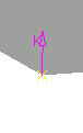
![]()
Visualize the Technological and Axis Representation
You can use this mode to visualize the technological and axis representation in the 3D area.
Click Technological & Axis Visualization
 .
.
The Technological & Axis Visualization dialog box is displayed. It displays the list of selected fasteners and the grayed out options that correspond to the selected mode. Selected fasteners are highlighted in the 3D area, you can remove a fastener using the contextual menu in the dialog box. The Preview button allows you to visualize the selected fasteners in the 3D area.
Here is how the fasteners are visualized in the 3D area:

![]()
Visualize the Fasteners Using a Customized Representation
You can choose explicitly a user-defined combination of symbols to be applied to a selection of fasteners.
Click Customized Visualization
 .
.
The Customized Visualization dialog box is displayed.
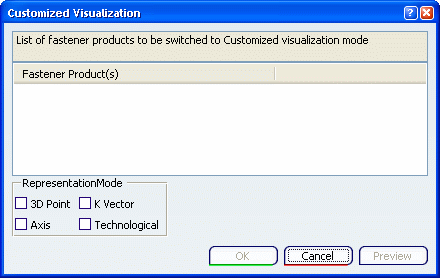
It displays the list of selected fasteners. Selected fasteners are highlighted in the 3D area, you can remove a fastener using the contextual menu in the dialog box. Visualization modes are all available for modification.