About Constraints | |||||
|
| ||||
![]()
Viewing Constraints
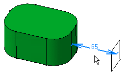
You can view the constraints applied on the elements.
- The application does not display constraints when these are too small. More precisely, the constraints visualization depends on the types of constrained elements. This means that when zooming out, a constraint set between two points is more likely to disappear than a constraint between two lines.
- You cannot view constraints if the plane in which they are located is normal to the screen. In that case, you just need to use the mouse, for example, to rotate the view and therefore make the constraints visible.
![]()
Changing Constraint Appearance
You can change the appearance of constraints by customization.
Here are the possible ways of changing constraint appearances.
Display mode
When setting constraints, four display mode are available as explained in the Customizing section of the Infrastructure User's Guide. Later, you can change display modes by selecting the constraint of interest and choose one of the following contextual commands.
-
Value Display: only the constraint (or parameter) value is displayed.
-
Name Display: only the constraint (or parameter) name is displayed.
-
Name/Value Display: the constraint (or parameter) name and value are both displayed.
-
Name /Value/Formula Display: the constraint (or parameter) name and value are displayed as well as the possible formula defined for this constraint.
Permanent Display
It is possible to permanently display the parameters of Part Design features as well as the valued constraints of Sketcher elements by selecting the feature and using the XXX.object >Edit Parameters contextual command.
Provided that the Parameters of features and constraints option has been previously selected in the Options dialog box, (for more information see Display in the Customizing section of the Part Design User's Guide), the following dialog box appears:

If you validate the option, parameters or constraints attached to the selected feature are permanently displayed in the 3D area.
Colors
To change the color of a given constraint, either you use the Properties contextual command or the Edit > Properties > Graphic (tab) command. You then just need to choose a color from the list (or you can define your own colors by selecting the More Colors... at the bottom of the color list. To know more about defining personal colors, see Infrastructure User's Guide.

If you wish to change the color for a given status, use Tools > Options. For more, see the Infrastructure User's Guide.


