Measuring Geometric Properties | |||
| |||
Select Measure Item
 in the Review Creation
toolbar.
in the Review Creation
toolbar.Several things now happen:
-
The arrow pointer
 changes
to the measure pointer
changes
to the measure pointer
 . Depending on the position of the measure pointer, it will
also show a symbol indicating the object you can select
with it. For a list of all the measure pointers, see
Pointer Transformation.
. Depending on the position of the measure pointer, it will
also show a symbol indicating the object you can select
with it. For a list of all the measure pointers, see
Pointer Transformation.
-
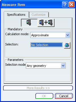
The Measure Item dialog box appears with the Specifications tab activated and Customize tab grayed out:
-
Move the measure pointer
over the geometry.
As you do this, the symbol to the bottom right of the pointer changes to reflect the geometry type and to help you with your selection. Also, dynamic highlighting of geometric entities helps you locate the item to be selected.
Click when the pointer is above the object whose geometric properties you want to measure.
Several things now happen:
-
The selected object is highlighted in the geometry and in the specification tree.
-
An information box appears, providing information about the properties of the selected geometry. Drag this box to move it. A full list of detectable objects is provided in Pointer Transformation. Here are some examples:
A plane A surface
 A volume
-
The Customize tab and More Results >> section in the Measure Item dialog box are now activated and both the geometry type and name of the object you selected are indicated in the Selection field.
-
A Measure item is created in the specification tree under the Notes branch with the name Measurexxxx.y where xxxx is the selected geometry type and y the number of measures made under the same slide and for the same type of geometry:
Important: - The symbol
appears when a measure is created in design mode.
The symbol
 appears when the measure is not associated with
the selection you made and will therefore not be affected
by any modifications you make to the selection.
appears when the measure is not associated with
the selection you made and will therefore not be affected
by any modifications you make to the selection.The symbol
 appears with an associative Measure, if the linked geometry
is not in design mode.
appears with an associative Measure, if the linked geometry
is not in design mode. - To rename the Measure, right-click it and change the name in the Properties dialog box.
- The symbol
-
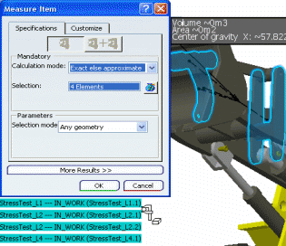
Using the same method as just described, select several geometric entities:
Important: - You cannot multiselect entities of different types.
After your first selection, you will only be able to select
a similar entity. The
 symbol appears in those areas where no selection is possible.
 - With the Multiple Measure mode you can create several measurements independently of each other without clicking the Measure Item several times . Each click on a measurable element will create a new Item measurement.
- Note that whereas for a single selection the information box is directly attached by an arrow to the selected entity, for a multiselection it is attached to the intersection of the dashed lines coming from the center of each selected entity.
After the second selection, the contents of the Selection field change to show only the number of selected entities.
- You cannot multiselect entities of different types.
After your first selection, you will only be able to select
a similar entity. The
To see a detailed list of your selections, click the
 button to the right of the Selection field.
The Measure Selections dialog box appears:
To remove any selections in the list, select the unwanted line(s) and click Remove. You can also do this by reclicking the selected entity in the geometry.
Note that you cannot remove all selections.
At each selection (or selection removal), the related information changes interactively in the More Results>> section:
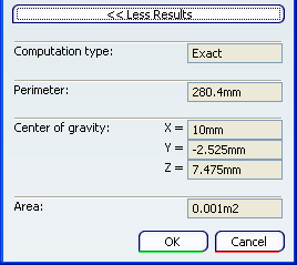
This information also appears in the information box:
The corresponding measures are added under the Notes item in the specification tree:
To edit an existing measure, you have three options:
-
Double-click the measure in the specification tree.
-
Double-click the information box in the geometry
-
Right-click the measure in the specification tree and, in the contextual menu that appears, select [measure_name] object>Definition... .
Once created in the specification tree, the selections of non-associative measures cannot be modified. If you click the
button, a warning message appears:
If you click Yes, all the selections will be removed from
the list in the Measure Selections dialog box. You can now
make new selections.
If you click No, the selection list remains unchanged.
Note that you can reopen any Measure to access the Customize
tab and the Results section.-
Important:
|