Remeshing Domains | |||||
|
| ||||
To remesh domains with the frontal quadrangle mesh method, click Frontal Quadrangle Method
 .
.
The Frontal Quadrangle Method dialog box appears.
- Select the domains in sequence.
- Enter a value of mesh size
- Click OK.
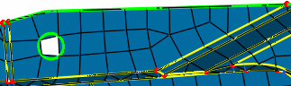
Example of a domain remeshed with the frontal quadrangle method:
To remesh domains with the frontal triangle mesh method, click Frontal Triangle Method
 .
.The Frontal Triangle Method dialog box appears.
- Select the domains in sequence.
- Enter a value of mesh size
- Click OK.
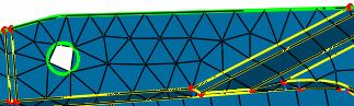
Example of a domain remeshed with the frontal triangle method:
To remesh a domain with the mapped mesh method, click Mapped Method
 .
.The mapped method generates a mesh as regular as possible using quadrangle elements only. The Mapped Method dialog box appears.
- Select the domain to remesh.
You can select domains with a rectangular, cylinder, or ring topology.
For domains with a rectangular topology, the C0, C1, C2, and C3 symbols are displayed on the selected domain to represent the four corners of the domain, even if the selected domain has more than four corners.
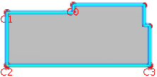
The four corners are automatically positioned, but you can change their positions to enhance the mesh quality. To change the position of a corner, select the corner you want to change, and then, select another vertex.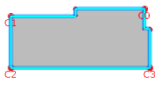
For domains with a cylinder or ring topology, corners are imposed and not displayed; you cannot modify them.
- Select the domain to remesh.
To remesh a domain with the mapped free mesh method, click Mapped Free Method
 .
.The mapped free mesh method generates a mesh as regular as possible using both quadrangle and triangle elements. The Mapped Free Method dialog box appears.
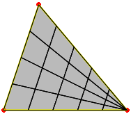
Example of a triangular domain remeshed with the mapped free method:
To remesh a domain with the minimal mesh method, click Minimal Method
 , and select the domain.
The minimal mesh method uses the existing nodes and topology constraints, and no internal nodes are created. The Minimal Method dialog box appears.
- Select the domain to remesh.
- If you work with a domain with a triangular topology, select the 3-side domain check box.
- Click OK.
To remesh a domain with the bead mesh method, click Bead Method
 , and select the domain.
The Bead Method dialog box appears.
- Select the domain to remesh.
At least two vertices are needed. The C0 and C1 symbols appear on the selected domain:
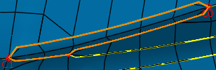
To change the position of a corner, select the corner you want to change, and then, select a vertex.
- Select the domain to remesh.
To remesh a domain with the half bead mesh method, click Half Bead Method
 , and select the domain.
The Half Bead Method dialog box appears.