Specification Tree | ||
| ||
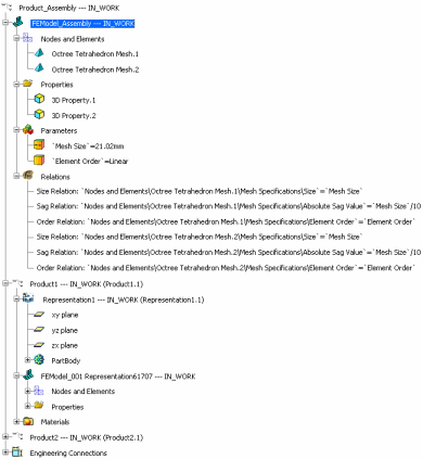
Tree Structure of Finite Element Model Representations
The following picture represents a typical specification tree for a finite element model representation:
![]()
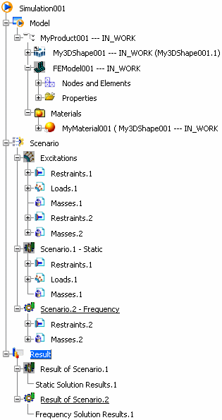
Tree Structure of Structural Analysis Simulations
The specification tree of a structural analysis simulation is
composed of three main categories: Model,
Scenario, and Result. The following
picture represents a typical specification tree for a structural analysis simulation.
![]()
Tree Symbols
The data in the Model, Scenario, and Result categories are linked and interrelated. Modifying an entity that is linked to a scenario or a result of scenario can change the update status of the scenario or the result of scenario. The  ,
,![]() , and
, and ![]() symbols that are displayed in the specification tree help you determine the relationships between the data.
symbols that are displayed in the specification tree help you determine the relationships between the data.
To learn more about those symbols, refer to Structural Analysis User's Guide: Creating Structural Analysis Simulations: About Structural Analysis Simulations.