Creating Constraint Areas | |||
| |||
Create Constraint Areas from a Face
You can create constraint areas from a face to define areas for routing, for placing components.
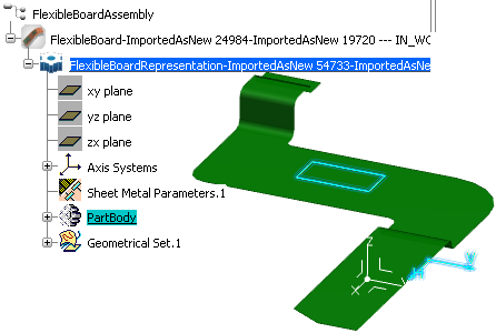
Click Constraint Area
 .
.
The Constraint Area dialog box is displayed.
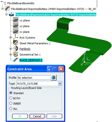
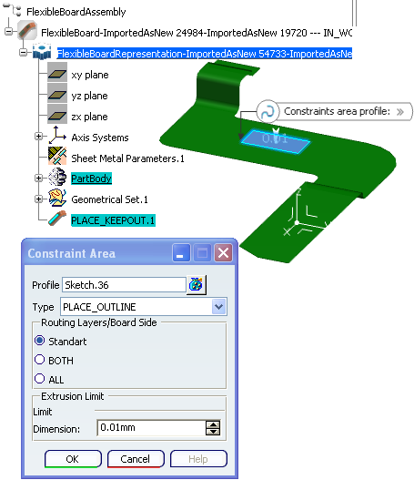
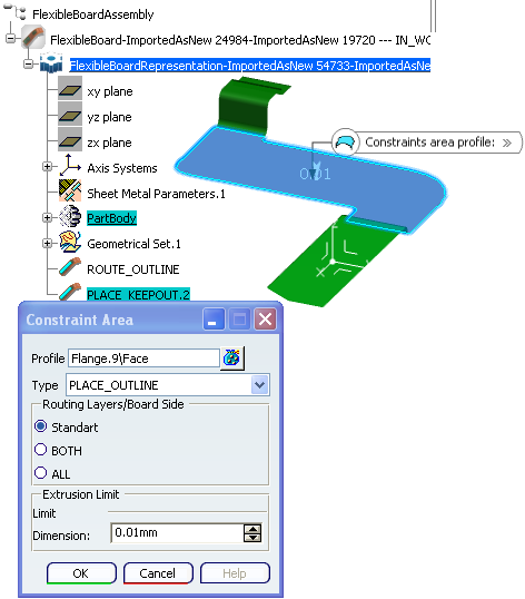
Select a Type of constraint area one or several surfaces.
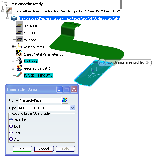
Click OK.
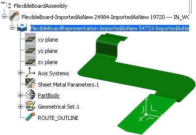
The face you selected turns to light green:
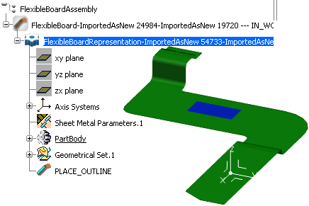
Select a face:
Click OK and the selected face will get another color:
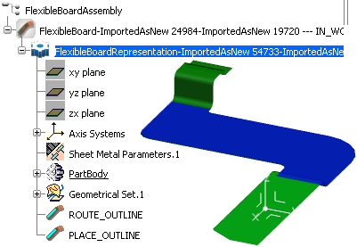
Note: Each Type has a specific color. You can double-click a constraint area to edit it and the Constraint Area dialog bow will open.
 to create a sketch on a face.