Electrical Data Exchange Format | ||
| ||
Introduction
iXF is an XML-based format defined by Dassault Systèmes, which is used for data exchange within CATIA. Briefly, iXF uses the SOAP (Simple Object Access Protocol) encoding format and relies on XML and XML Schemas. It lets you describe a specific data model (a grammar) using objects, classes and behaviors as well as documents containing data that conform to the defined grammar.
The iXF electrical schema for data exchange between CATIA V6 electrical products and external applications (CAA partner applications, etc.) describes a subset of electrical objects together with their relations.
This schema is based on the fact that an object is defined as a class, which is associated to a behavior set. Thus, an electrical connector corresponds to the Connector class, to which Connector and Product behaviors are associated.
| Warning: The data exchange model is different from the data model used by CATIA electrical solutions. It contains the pertinent information (objects, attributes and connectivity) that needs to be imported from electrical specification tools into CATIA only. The electrical schema does not therefore contain all the information stored in CATIA electrical product documents. |
![]()
Electrical Objects
This table describes the electrical objects and the behavior type that can be associated to them.
| Class | Associated Behavior |
|---|---|
| Electrical Geometry |
|
| Conductor |
|
| Equipment |
|
| ConnectorShell |
|
| BackShell |
|
| Splice |
|
| Pin |
|
| Cavity |
|
| Accessory |
|
Note: All the objects in the iXF schema, except for objects of the Link type, have an attribute identifying the object in a unique way within the project. Objects of the Link type have a unique identifier within the document.
You can add the Device Link between the Shell and Cavities in the iXF file. You can add this type of device in the iXF file:
- Accessory:
iXF Attributes Database Attributes Name Name of the Accessory Id Instance Name PartNumber Reference Name SubType SubType - BackShell:
iXF Attributes Database Attributes Name Name of the BackShell Id Instance Name PartNumber Reference Name SubType SubType
To illustrate how to describe an electrical object with the iXF
format, let's take the example of an electrical connector:
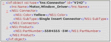
This electrical connector of Connector class has:
- As identifier: V242 (attribute 'id')
- As name: Motor,Window_Driver (attribute 'Name')
- As reference: 5584555 -5W (attribute 'PartNumber' via its Product behavior)
- As subtype: Single Insert Connector (attribute 'SubType' via its Connector behavior)
- As color: Yellow (attribute 'Color' via its Connector behavior)
![]()
Relations between Electrical Objects
Relations between nearly all electrical objects are managed via objects with Link type behavior. Relations between two connectors are managed via a specific attribute.
Link type Behavior
Nearly all the relations between electrical objects take the form of objects with a Link type behavior.
The Link object classes of the electrical schema
are:
- WireLink
- DeviceLink
- HarnessLink
These object classes allow you to define:
- Conductor connectivity, i.e. connections with electrical components (instantiated standard parts).
- Aggregation relations between electrical components (instantiated standard parts). For example, a connector with cavities or an equipment with connectors and cavities.
- The composition of the electrical geometry (conductors and electrical components).
These links take the form of identifiers. For example: a conductor, whose identifier is W1, connected to two electrical cavities, whose identifiers are C1 and C2. Here is an example of iXF syntax:
<ixf:object xsi:type="tns:Equipment" id="MyEQT_1">
     <tns:Name>MyEQT_1.1</tns:Name>
     <NS1:Product>
       <NS1:PartNumber>EQT_A</NS1:PartNumber>
     </NS1:Product>
 </ixf:object>
 <ixf:object xsi:type="tns:Cavity" id="MyEQT_1.1@MyEQT_1@Cavity.1">
     <tns:Name>MyCavity.1</tns:Name>
 </ixf:object>
 <ixf:object xsi:type="tns:DeviceLink" id="DeviceLink_1">
     <NS2:link>
        <NS2:object1 href="#MyEQT_1"/>
        <NS2:object2 href="#MyEQT_1.1@MyEQT_1@Cavity.1"/>
      </NS2:link>
 </ixf:object>
 <ixf:object xsi:type="tns:ConnectorShell" id="ConnectorShell_1">
     <tns:Name>ConnectorShell_1.1</tns:Name>
     <NS1:Product>
        <NS1:PartNumber>SHELL_1</NS1:PartNumber>
     </NS1:Product>
 </ixf:object>
 <ixf<tns:Name>Cavity.1</tns:Name>:object xsi:type="tns:Cavity"
              id="ConnectorShell_1.1@ConnectorShell_1@Cavity.1">
     <tns:Name>Cavity.1</tns:Name>
 </ixf:object>
 <ixf:object xsi:type="tns:DeviceLink" id="DeviceLink_1">
    <NS2:link>
       <NS2:object1 href="#ConnectorShell_1"/>
       <NS2:object2 href="#ConnectorShell_1.1@ConnectorShell_1@Cavity.1"/>
    </NS2:link>
 </ixf:object>
 <ixf:object xsi:type="tns:Wire" id="Wire_1.1">
    <tns:Name>Wire_1.1</tns:Name>
    <NS1:Product>
       <NS1:PartNumber>Wire_1</NS1:PartNumber>
    </NS1:Product>
 </ixf:object>
 <ixf:object xsi:type="tns:WireLink" id="Link_1">
    <NS2:link>
      <NS2:object1 href="#Wire_1.1"/>
      <NS2:object2 href="#MyEQT_1.1@MyEQT_1@Cavity.1"/>
    </NS2:link>
 </ixf:object>
 <ixf:object xsi:type="tns:WireLink" id="Link_2">
   <NS2:link>
      <NS2:object1 href="#Wire_1.1"/>
      <NS2:object2 href="#ConnectorShell_1.1@ConnectorShell_1@Cavity.1"/>
    </NS2:link>
      </ixf:object>
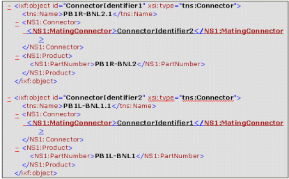
Specific Attribute
The relation between two connectors (mating connector, connector) is not managed by a Link object as above but using a specific attribute named MatingConnector (behavior attribute of Connector type). This attribute is optional and is valuated with the identifier of the mating connector on both sides of the connection.
Let see an example where two connectors are connected together. The
connectivity between them is described as follows: