More about Connecting Electrical Devices | ||||
|
| |||
When connecting devices, if selected devices are not located in the same electrical geometry, the context is defined by the parent common to the electrical geometry and all already-connected devices in the geometrical harness. If you subsequently select a device outside this context, the system proposes to automatically update the context for you.
When you make an electrical connection between two devices:
- An electrical link is created between the connected components.
- If placement constraints have been defined on connection points, mechanical assembly constraints are automatically created.
For information about which connection is associated to which component, see the table below.
You can face four different use cases when creating contextual connections. During the connection process the context environment controls the way the devices move.
Context changes are explained in the table here below:
| Connection Type | Device Behavior / Context |
|---|---|
| Standard Connection | Please see Connectable Devices Reference Table |
Two devices are under two different father geometrical harnesses. |
The first selected device moves.
The first selected father device defines the context. |
Only one of the two devices is under an electrical geometry. |
The device under the Electrical Geometry moves and defines the context. Note: This behavior applies to any type of device. |
| None of the devices is under an Electrical Geometry. | The Standard Connection applies.
Please see Connectable Devices Reference Table. |
Note:
When you make an electrical connection between two devices:
- An electrical link is created between the connected components.
- If placement constraints have been defined on connection points, mechanical assembly constraints are also automatically created.
When two connected electrical devices belong to the same parent and their assembly constraints have been created via the Connect Devices command, the No check option is automatically checked. If you double-click an engineering connection, it can be edited in the Interferences tab of the Engineering Connection Definition dialog box: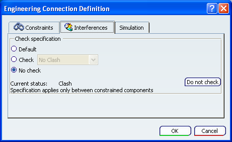
The No check option is used to improve clash analysis performance.