About Orientation Management | ||
| ||
To be able to handle the torsion of flat cable, the following information is needed:
- like any other branch, the flexible curve is needed as guide
- the profile (rectangular with width and thickness values) is needed to be swept
- orientations of each point computed on the curve are necessary to orient the profile along the curve
These orientations are calculated by FLEX algorithm and can be retrieved from its result. This is why flat cables need to be designed with FLEX algorithm active. For more information, please refer to the Electrical 3D Installation User's Guide: Using the FLEX Algorithm.
If you want to change the flat cable's orientation, you can use the Rotate command to define a new reference axis and / or a new rotation angle for each point. For more information, please refer to Electrical 3D Installation User's Guide: Working with Segments: Using the Rotate Command on Flat Cables. The difference between regular branches and flat cables is that the orientation can also be imposed by default in some cases (see table below). The orientation is defined by:
- a reference axis (around which the profile will be rotated). This reference axis must be chosen inside the plane normal to curve tangency and depends on the routed object.
- a rotation angle. The profile will be then rotated on the basis of the reference axis, rotation being inside the plan normal to cure tangency.
If the rotation angle is null, the reference axis is collinear to the flat cable Thickness (this is the default behavior):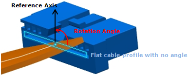
| Type of routed component | Support | Segment connection point | Route Point | ||
|---|---|---|---|---|---|
| Retainer | Standard | Standard | Advanced | ||
| Orientation is imposed by default when routing on | Yes* | Yes* | Yes* | Yes*** | No |
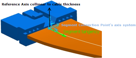
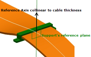
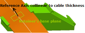
| Default reference axis to compute angle to (if not specified by the user) | Line perpendicular to base plane (see image 3 below) | Support reference line** (see image 2 below) | Z axis of the axis system (see image 1 below) | V direction of the plane normal to segment connection point tangency. | V direction of the plane normal to curve at point |
*: The default rotation angle is 0 degree and the flat cable thickness is collinear to the reference axis.
**: This reference line is automatically defined inside the first support's reference plane. It also corresponds to the internal X axis of the support.
***: If no tangency is defined (only in this case), orientation is not imposed, the flat cable is then free at this point.
(Image 1)
(Image 2)
(Image 3)