Creating a Device Section View | |||
| |||
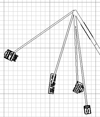
Create a 2D view of your flatten geometry using Front View
 .
.
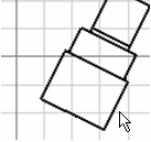
Click Device Section View
 in the Electrical
Dress-Up toolbar.
in the Electrical
Dress-Up toolbar.
Click the desired device. Note that the section will be made in the direction of the device part you selected (here, the right side of the device).
Click the sheet to show the section view.
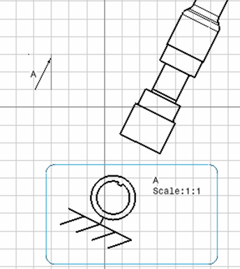
- The A arrow indicates the direction in which the section has been made. You can move the section view in this direction only.
- The stripped 2D detail is the table reference to help you visualize the section view. To obtain this symbol, you have to import it in the catalog as a reference using the following path: intel_a\startup\Electrical\Drawing\Table_Reference.3dxml.
This view only shows a view of all the connectors linked to the selected device. For more information, see Generative Drafting User's Guide.