Click Ellipse
 in the Profile toolbar (Conic sub-toolbar).
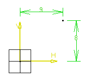
 Click in the geometry area to locate the first point of the profile, or if you know where this point must be located, use the Sketch tools toolbar which now displays value fields for first defining the ellipse center point, major and then minor semi-axis endpoint.
These value fields are:
-
Center: H: horizontal
-
V: vertical
-
Major Radius
-
Minor Radius
-
A: angle
-
Position the cursor in the desired fields and key in the desired values. For example, enter:
- Center (H: 9mm and V: 8mm)

Note that you can also click to create a first point that corresponds to the ellipse center.
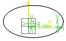
- Major Semi-Axis Endpoint (H: 65mm and V: 8mm)
You just created a point on the ellipse. This point allows defining the major semi-axis.

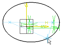
Move the cursor and click a point on the ellipse. You just created a point which allows defining both minor semi-axes.

Tip: Constraints are assigned to the ellipse on the condition that: - You activated Dimensional Constraints
 in the Sketch tools toolbar before starting the
scenario.
 - You entered coordinate values in the fields (you did not create the profile just by clicking).
Important: - In this task we used the toolbar but you can create this ellipse manually. To do this, move the cursor to activate SmartPick and click as soon as you get what you wish.
- By default, centers are created and are associative but
if you do not need them you can specify this in the Tools
> Options dialog box. For this, select
Tools > Options > Mechanical Design > Sketcher
(Sketcher tab). For more information, see the
Infrastructure user's guide.

- You activated Dimensional Constraints