Modifying Constraints | |||||
|
| ||||
Edit Sketcher Constraints
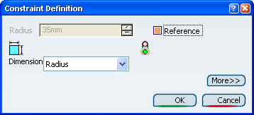
You can modify the constraint using the Constraint Definition dialog box.
Double-click the radius constraint.
The Constraint Definition dialog box appears.Select the Reference check box to make the constraint a reference .
The Radius field is deactivated, indicating that the value is now driven by modifications to the sketch.
Using the Reference mode, the offset value is displayed between brackets indicating this mode and measured from the component locations. When the offset constraint supporting elements are two non-parallel lines or the offset constraint is over-constrained, the offset value cannot be measured, the constraint is invalid, any value is displayed and two pound signs are displayed between the brackets (##).
Click OK to confirm.
The radius value is displayed in brackets in the geometry area.
Type 125 deg and click OK.
The new value is displayed in the geometry area. It affects the angle. The sketch shape is also modified due to the radius previously converted into a measure.
Click the More button to access additional information.
Click OK.
The position of the profile is modified accordingly.
Exit the Sketcher.
The application has integrated the modifications to the sketch.
Important: When you are in the Repeat mode (you double-clicked on the command for creating a constraint), if you try to edit an existing constraint while creating another constraint, the modification will only be taken into account when you have finished creating this other constraint.
![]()
Modify Constraint Values by Using the Shift Key
It is possible to edit dimensional constraint values just by dragging constrained geometry. This is a quick way of editing constraints without launching dialog boxes.
Press the Shift key and drag the vertical line to the right as shown below.
You can notice that the value of the angle constraint is not only modified as you are dragging the cursor, but it is also displayed between parentheses, meaning that it is temporarily converted into a reference. In other words, you can move the geometry freely, with respect to geometric constraints.
Press the Shift key and drag the vertical line to the right as shown below.
The modified angle value is displayed (137.913), and is no longer a reference:
If Snap to Point
 is active, the geometry is moved according to the
spacing you defined for the grid. For more information, see the
customization section of the Sketcher.
is active, the geometry is moved according to the
spacing you defined for the grid. For more information, see the
customization section of the Sketcher.
![]()
Deactivate or Activate Constraints
To deactivate a constraint, right-click the constraint and select xxx.N.object > Deactivate.
Right-click the constraint and select xxx.N.object > Deactivate. This constraint will still appear on the sketch but will not behave as such.
Deactivated constraints appear preceded by an open-close brackets symbol in the geometry and in the specification tree.