Mirroring Elements | |||
| |||
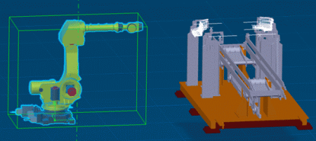
Select the element to be mirrored.
If you want to mirror more than one element, select the elements before clicking the command.
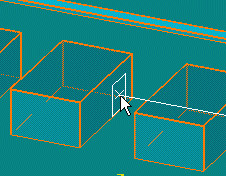
Place your cursor over a geometric element that defines the plane (for example, a construction plane).
As you move the cursor, a small white rectangle is displayed to show the selectable planes, as shown below.

If you do not see the white rectangle, zoom out from the drawing. The white rectangle cannot be displayed if the element under your cursor is displayed too small.

Click to select the plane.
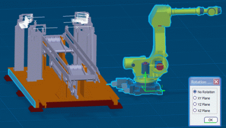
The selected elements are moved to the other side of the plane at their mirror location.

A green axis is displayed at the element origin and a dialog box appears for defining the orientation of mirrored elements.
The Rotation dialog box options are as follows:
- No Rotation: The element will only be placed at the mirror position.
- XY Plane: The element will be placed at the mirror location and then rotated 180 degrees about the Z axis. Using this option makes the Z axis red.
- YZ Plane: The element will be placed at the mirror location and then rotated 180 degrees about the X axis. Using this option makes the X axis red.
- XZ Plane: The element will be placed at the mirror location and then rotated 180 degrees about the Y axis. Using this option makes the Y axis red.
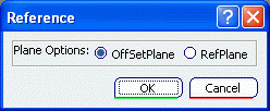
Note: If you already have a reference plane defined (see Using Offset Planes), clicking Mirror
 provides an option for using it.
Select Offset Plane to use the existing plane. Alternatively you can select Ref Plane to define a new plane for the mirror.