Measure Between Dialog Box | ||
| ||
Measure Between
This dialog box has two tabs and enables you to measure objects.
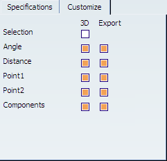
Specifications
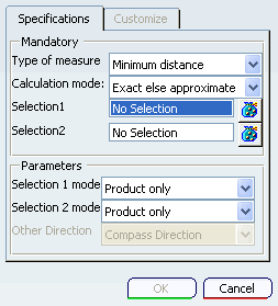
The Specifications tab of the Measure Between dialog box enables you to specify the geometry and other attributes of the measurement you want.
In the Mandatory pane, you can choose:
- Type of measure
- Minimum distance, which measures the smallest possible distance between the two selections.
- Measure along a distance, which measures the distance the selected geometry moves along a specified direction.
- Calculation mode:
- Exact else approximate (default), which measures exact data and, wherever possible, gives true values. If exact values cannot be measured, approximate values are given (identified by a ~ sign).
- Exact, which measures exact data, and gives true values.
- Approximate, which measures tessellated objects and gives approximate values (identified by a ~ sign).
- Selection1 or Selection2, which can consist of:
- a single geometric entity that you select from the Specification tree or the geometry itself.
- multiple items, which you select by clicking the items in the 3D view. To facilitate multi selecting, you can also use Groups
 .
.
In the Parameters pane, you can choose:
- Selection1 mode or Selection2 mode, which filters the types of geometry you select.
- Any geometry (default mode), which measures distances and, if applicable, angles between defined geometric entities (points, edges, surfaces, etc.).
- Any geometry, infinite, which measures distances and, if applicable, angles between the infinite geometry (plane, line or curve) on which the selected geometric entities lie. Curves are extended by tangency at curve ends. If an arc is selected in Any geometry, infinite, note that the arc edge is measured and not the arc center.
- Picking point, which measures distances between points selected on defined geometric entities.
- Point only, which measures distances between points. Dynamic highlighting is limited to points.
- Edge only, which measures distances and, if applicable, angles between edges. Dynamic highlighting is limited to edges and is thus simplified compared to the Any geometry mode. All edge types are supported.
- Surface only, which measures distances and, if applicable, angles between surfaces. Dynamic highlighting is limited to surfaces and is thus simplified compared to the Any geometry mode.
- Product only (default mode), which measures distances between Products. Products can be specified by selecting Product geometry, for example an edge or surface, in the geometry area or the specification tree.
- Other Direction, which specifies the direction along which the measurement is made. This option is only available if you selected Measure along a distance for Type of measure. The directions you can select are:
- Compass direction (default mode)
- X axis, Y axis, or Z axis.