Inserting a Behavior in an Existing Function/Logical Component | |||
| |||
Select Insert a Logical Behavior
 from the Behaviors toolbar.
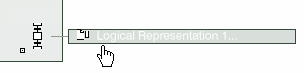
From the RFLP structure tree or from the 2D graph representation, select a logical component.
The Behavior dialog box appears.
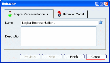
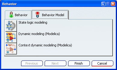
Open the Behavior Model tab to select a modeling type.
Warning: The modeling selection is different for a function or for a logical component. In a function, you can only use the state logic modeling.
In a logical component, you can select:
- State logic modeling
- Dynamic modeling (Modelica)
- Context dynamic modeling (Modelica)
For more about these behavior types, read About behaviors.
Click Finish to close the dialog box.
The behavior representation is created under the selected logical component.
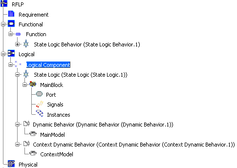
It contains a node (MainBlock, MainModel or ContextModel) that represents the behavior.
Also note that a behavior icon is inserted in the 2D representation of the logical component (at the bottom right).