Select Class Attributes  .
.
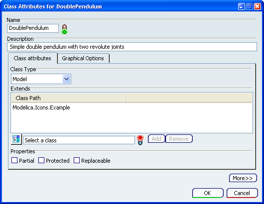
The Class Attributes dialog box appears and displays the attributes of the active class.
If there is any description associated to the class, it is displayed from the Description field.

If needed, modify the class name in the Name field.
On the Class attributes tab, select a class type from the Class Type box. For the purpose of this scenario, select Type.
From the Extends area, click Switch between class and basic type selection  .
.
Select Real as a basic type then click Add.
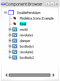
The Real basic type is added to the Class Path list.

Optional: From the Properties area, select Partial, Protected or Replaceable.
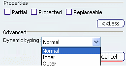
Click the More button to display the Dynamic typing box.

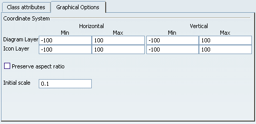
Click the Graphical Options tab.

The options on this tab let you define the coordinate system properties of the diagram and the icon layers. The coordinate system is represented by a frame on both layers. Preserve aspect ratio and Initial scale are applied to components instantiated from a class.
Enter the minimum and maximum horizontal and vertical values for both layers to define the frame.
Select the Preserve aspect ratio check box to keep the aspect ratio when resizing a component in the diagram layer.
In the Initial scale box, define the initial scale for a component.
Click OK to exit the dialog box and save the new class attributes.
