Manipulating Objects Using the Edit... Command | |||||
|
| ||||
Open any document with geometrical data.

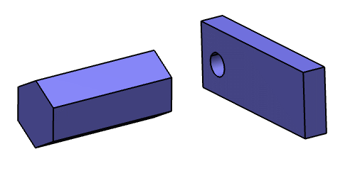
Drag and drop the Robot onto an object.
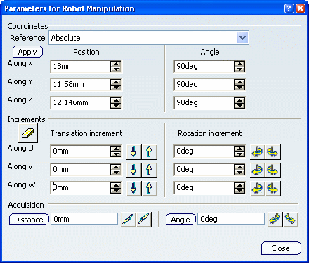
Right-click the Robot then select Edit (you can also double-click the Robot).

The Parameters for Robot Manipulation dialog box stays open during manipulation.
Important: The current coordinates of the manipulation handle (i.e. the blue cube), with respect to the center of the 3D scene, are displayed in the corresponding boxes for the Position option. In our example, the center of the 3D scene is the point of intersection of the 3 planes located on the pad. In the Coordinates area, select the axis system with respect to which you will edit the coordinates of the Robot.
Reset the X, Y and Z coordinates of the Robot to zero, using the Position options, then click Apply.
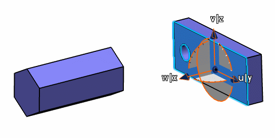
In our example, because you dropped the Robot onto an object, the Robot and the object are moved to the center of the 3D scene as follows:

To translate the Robot and the object by increments along an individual axis (U, V or W), set the translation values for an axis, then click
 or
or
 .
.The Robot and the object are translated in forward or reverse direction, respectively.
When an axis is highlighted, it remains so until:
- You highlight another axis by clicking it with the mouse.
- You move the Robot to another location using any interaction other than a click on one of the increment buttons.
- You close the Parameters for Robot Manipulation dialog box.
Warning: Increment options can be used in the Part Design workbench but axes are not highlighted. Click Distance in the Acquisition area and select two elements.
The object is translated along a vector derived from the two objects you selected.
The value for the detected distance is highlighted in the appropriate boxes, expressed in the units of the Robot. Depending on the Robot orientation, some or all of the X, Y and Z coordinates might be calculated.
- If the first element is a line or a plane, you can then select a second element or enter a distance. For example, selecting a line implies that you want to translate the object in the direction of the line, and you can enter the distance for the translation in the Distance box. However, if you just select the two elements, the distance between the two is displayed in the Distance box, and the object will be translated over this distance and in the same direction.
- If the second element is a plane, the direction of translation is normal to the plane.
Click either
 or
or
 to the
right of the Distance box.
to the
right of the Distance box.The object is translated in reverse or forward direction, respectively.
Set a rotation angle and click
 or
or
 for the axis about which you want to rotate.
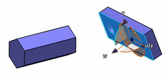
For example, with the object still located at the center of the 3D scene, rotating about the U axis produces this result:

Click Angle and select two elements.
The object is rotated through the angle between the two elements (you can select a line or a plane). The angle value is displayed in the Angle box.
If the rotation axis is parallel to one of the Robot's axes, the value is also displayed in the appropriate box in the Rotation increment area, the 2 other ones being reset to 0.
Click
 or
or
 .
.
The Robot and the object are rotated about the computed rotation axis.
Important: The values you enter in the Rotation increments area and in the Acquisition area have no impact on each other. For instance, if you enter an increment value in the Along U box then click  ,
the increment will not be taken into account.
The
Rotation increments values let you rotate the object about an axis
and the Angle box in the Acquisition area lets you specify
a rotation angle between two elements you select.
,
the increment will not be taken into account.
The
Rotation increments values let you rotate the object about an axis
and the Angle box in the Acquisition area lets you specify
a rotation angle between two elements you select.Optional: When the Robot is snapped to the object, drag its arcs.
The object is translated or rotated according to the increments you entered.
Click Close.
The increments are kept for the Robot and bounding box motions.
Optional: Access the Parameters for Robot Manipulation dialog box and set the direction value of your choice to 0.
The Robot is reset and you can move it freely according to the direction set to 0.